+86-13723477211
What are the product characteristics of aluminum electrolytic capacitors?
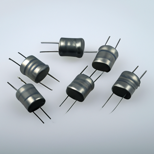
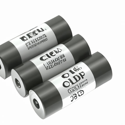
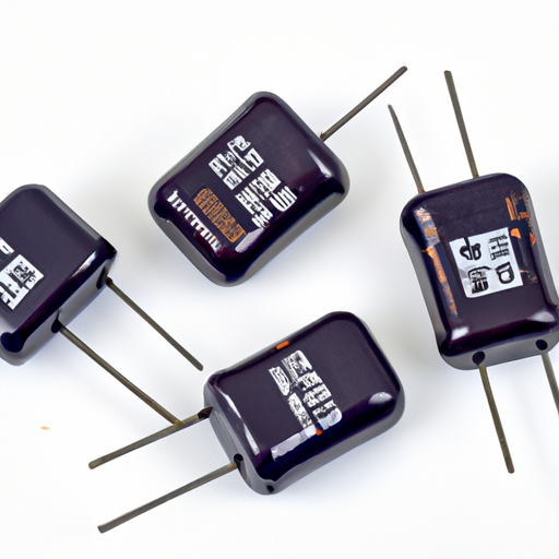
Product Characteristics of Aluminum Electrolytic Capacitors I. Introduction Aluminum electrolytic capacitors are essential components in modern electronic circuits, playing a crucial role in energy storage and signal processing. These capacitors are widely used due to their high capacitance values and cost-effectiveness, making them a popular choice in various applications, from power supplies to consumer electronics. In this article, we will explore the product characteristics of aluminum electrolytic capacitors, including their structure, electrical and performance characteristics, applications, advantages, and disadvantages. II. Basic Structure and Composition A. Anode and Cathode Materials The fundamental structure of aluminum electrolytic capacitors consists of two main components: the anode and the cathode. 1. **Aluminum Foil as Anode**: The anode is typically made from high-purity aluminum foil, which serves as the primary conductive element. The surface of the aluminum foil is treated to create a thin oxide layer, which acts as the dielectric material. 2. **Electrolyte as Cathode**: The cathode is formed by a liquid or solid electrolyte, which interacts with the oxide layer on the anode. The electrolyte can be a conductive solution or a polymer, depending on the capacitor's design and intended application. B. Dielectric Layer Formation The dielectric layer is a critical component of aluminum electrolytic capacitors. 1. **Oxide Layer Creation**: The oxide layer is formed through an electrochemical process known as anodization. This process involves applying a voltage to the aluminum foil, which causes aluminum oxide to grow on its surface. The thickness of this layer directly influences the capacitor's voltage rating and capacitance. 2. **Role of the Electrolyte**: The electrolyte not only serves as the cathode but also plays a vital role in maintaining the integrity of the dielectric layer. It facilitates the movement of ions, which is essential for the capacitor's operation. C. Physical Dimensions and Form Factors Aluminum electrolytic capacitors come in various physical dimensions and form factors to suit different applications. 1. **Cylindrical Capacitors**: The most common form factor is the cylindrical capacitor, which features a metal canister that houses the anode and cathode materials. These capacitors are often used in power supply circuits due to their robust design. 2. **SMD Capacitors**: Surface-mount device (SMD) capacitors are designed for automated assembly processes. They are smaller and have a flat profile, making them suitable for compact electronic devices. III. Electrical Characteristics A. Capacitance Values Aluminum electrolytic capacitors are known for their high capacitance values. 1. **Range of Capacitance**: These capacitors typically range from a few microfarads (µF) to several thousand microfarads, making them ideal for applications requiring significant energy storage. 2. **Tolerance Levels**: The tolerance of aluminum electrolytic capacitors can vary, with common values ranging from ±10% to ±20%. This variability is essential for designers to consider when selecting capacitors for specific applications. B. Voltage Ratings Voltage ratings are critical for ensuring the safe operation of aluminum electrolytic capacitors. 1. **Working Voltage**: The working voltage, or rated voltage, is the maximum continuous voltage that the capacitor can handle without failure. Exceeding this voltage can lead to catastrophic failure. 2. **Surge Voltage**: Surge voltage refers to the maximum voltage that the capacitor can withstand for a short duration. It is essential to consider surge conditions in applications where voltage spikes may occur. C. Equivalent Series Resistance (ESR) ESR is a vital parameter that affects the performance of aluminum electrolytic capacitors. 1. **Definition and Importance**: ESR is the internal resistance of the capacitor, which can lead to power loss and heat generation during operation. Lower ESR values are generally preferred for high-frequency applications. 2. **Impact on Performance**: High ESR can result in reduced efficiency and increased heat generation, potentially leading to premature failure of the capacitor. D. Leakage Current Leakage current is another important characteristic of aluminum electrolytic capacitors. 1. **Definition and Measurement**: Leakage current is the small amount of current that flows through the dielectric when a voltage is applied. It is typically measured in microamperes (µA). 2. **Factors Affecting Leakage**: Several factors can influence leakage current, including temperature, voltage, and the quality of the dielectric layer. Designers must account for leakage when selecting capacitors for low-power applications. IV. Performance Characteristics A. Temperature Stability Temperature stability is crucial for the reliable operation of aluminum electrolytic capacitors. 1. **Operating Temperature Range**: These capacitors typically operate within a temperature range of -40°C to +105°C, although some specialized capacitors can withstand higher temperatures. 2. **Effects of Temperature on Performance**: As temperature increases, the capacitance and ESR can change, affecting the overall performance of the capacitor. Designers must consider these variations when selecting capacitors for specific environments. B. Frequency Response The frequency response of aluminum electrolytic capacitors is essential for their performance in AC applications. 1. **Impedance Characteristics**: The impedance of a capacitor varies with frequency, and understanding this behavior is crucial for applications involving alternating current. 2. **Self-Resonant Frequency**: Each capacitor has a self-resonant frequency, beyond which its impedance decreases significantly. This frequency is an important consideration in high-frequency applications. C. Lifetime and Reliability The lifetime and reliability of aluminum electrolytic capacitors are critical factors for designers. 1. **Factors Influencing Lifespan**: The lifespan of these capacitors can be influenced by factors such as temperature, voltage, and ripple current. Operating within specified limits can help extend their lifespan. 2. **Failure Modes and Mechanisms**: Common failure modes include dielectric breakdown, electrolyte leakage, and corrosion of the anode. Understanding these mechanisms can help designers mitigate risks in their applications. V. Applications of Aluminum Electrolytic Capacitors Aluminum electrolytic capacitors are used in a wide range of applications, including: A. Power Supply Circuits These capacitors are commonly found in power supply circuits, where they smooth out voltage fluctuations and provide energy storage during peak loads. B. Audio Equipment In audio applications, aluminum electrolytic capacitors are used for coupling and decoupling signals, ensuring high-quality sound reproduction. C. Motor Drives Motor drive circuits utilize these capacitors for energy storage and filtering, helping to improve efficiency and performance. D. Consumer Electronics From televisions to smartphones, aluminum electrolytic capacitors are integral to the operation of various consumer electronics, providing stability and performance. E. Industrial Applications In industrial settings, these capacitors are used in automation systems, power distribution, and control circuits, where reliability and performance are paramount. VI. Advantages and Disadvantages A. Advantages 1. **High Capacitance Density**: Aluminum electrolytic capacitors offer high capacitance values in relatively small packages, making them ideal for space-constrained applications. 2. **Cost-Effectiveness**: Compared to other capacitor types, aluminum electrolytic capacitors are generally more affordable, making them a popular choice for manufacturers. 3. **Wide Availability**: These capacitors are widely available in various specifications, ensuring that designers can find suitable options for their applications. B. Disadvantages 1. **Limited Voltage Ratings**: Aluminum electrolytic capacitors have lower voltage ratings compared to other capacitor types, which can limit their use in high-voltage applications. 2. **Temperature Sensitivity**: Their performance can be significantly affected by temperature changes, requiring careful consideration in design. 3. **Polarity Issues**: These capacitors are polarized, meaning they must be connected in the correct orientation to function properly. Incorrect installation can lead to failure. VII. Conclusion In summary, aluminum electrolytic capacitors are vital components in modern electronic circuits, offering high capacitance values and cost-effectiveness. Understanding their product characteristics, including structure, electrical and performance attributes, applications, advantages, and disadvantages, is essential for designers and engineers. As technology continues to evolve, advancements in aluminum electrolytic capacitor technology will likely lead to improved performance and reliability, making them an enduring choice in the electronics industry. VIII. References 1. Academic Journals 2. Industry Standards 3. Manufacturer Specifications This comprehensive overview of aluminum electrolytic capacitors highlights their significance in electronic design and provides valuable insights for selecting the right components for various applications.
2025-02-20 01:07:58
0
What industries do capacitor formulas include?
What Industries Do Capacitor Formulas Include? I. Introduction Capacitors are fundamental components in electrical and electronic systems, serving as energy storage devices that can release energy when needed. They play a crucial role in various applications, from smoothing out voltage fluctuations in power supplies to enabling signal processing in communication devices. Understanding capacitor formulas is essential for engineers and designers across multiple industries, as these formulas help predict how capacitors will behave in different scenarios. This blog post will explore the significance of capacitors, the formulas that govern their behavior, and the diverse industries that rely on them. II. Understanding Capacitor Formulas A. Basic Principles of Capacitance At its core, capacitance is the ability of a capacitor to store an electrical charge. The basic formula for capacitance (C) is defined as: \[ C = \frac{Q}{V} \] where \( Q \) is the charge stored in coulombs, and \( V \) is the voltage across the capacitor in volts. Another important formula relates capacitance to the physical characteristics of the capacitor: \[ C = \frac{ε(A/d)} \] In this equation, \( ε \) represents the permittivity of the dielectric material between the capacitor plates, \( A \) is the surface area of the plates, and \( d \) is the distance between them. These formulas highlight the factors that influence capacitance, including the type of dielectric material used, the size of the plates, and their separation distance. B. Types of Capacitors Capacitors come in various types, each suited for specific applications: 1. **Electrolytic Capacitors**: Known for their high capacitance values, these capacitors are often used in power supply circuits. 2. **Ceramic Capacitors**: These are widely used in high-frequency applications due to their stability and low losses. 3. **Film Capacitors**: Known for their reliability and low self-inductance, film capacitors are used in audio and power applications. 4. **Tantalum Capacitors**: These capacitors offer high capacitance in a small package and are commonly used in portable electronics. C. Factors Affecting Capacitance Several factors can influence the capacitance of a capacitor: 1. **Dielectric Materials**: The type of dielectric material affects the capacitor's ability to store charge. Materials with higher permittivity allow for greater capacitance. 2. **Surface Area and Distance**: Increasing the surface area of the plates or decreasing the distance between them will increase capacitance. III. Industries Utilizing Capacitor Formulas Capacitors are integral to numerous industries, each leveraging capacitor formulas for specific applications. A. Electronics and Consumer Goods In the electronics sector, capacitors are essential for circuit design. They are used in smartphones, computers, and home appliances to filter signals, stabilize voltage, and store energy. For instance, in power supply circuits, capacitors smooth out voltage fluctuations, ensuring that devices operate efficiently and reliably. B. Automotive Industry The automotive industry has seen a significant shift towards electric vehicles (EVs), where capacitors play a vital role. Capacitors are used in energy storage systems, regenerative braking, and electric drive systems. Additionally, they are crucial in infotainment systems and safety features, such as airbags and anti-lock braking systems, where rapid charge and discharge cycles are necessary. C. Renewable Energy Sector Capacitors are increasingly important in the renewable energy sector, particularly in solar energy systems. They are used in solar inverters to manage the conversion of DC to AC power, ensuring efficient energy transfer. Capacitors also play a role in energy storage systems, helping to stabilize power output and improve grid reliability. D. Telecommunications In telecommunications, capacitors are vital for signal processing. They are used in mobile networks and data centers to filter signals, manage power supply, and ensure data integrity. Capacitors help maintain the quality of communication by reducing noise and stabilizing voltage levels. E. Industrial Automation The industrial automation sector relies heavily on capacitors in motor drives and control systems. Capacitors are used to improve the efficiency of electric motors, reduce energy consumption, and enhance the performance of robotics and manufacturing equipment. They help manage power supply and ensure smooth operation in automated processes. F. Medical Devices In the medical field, capacitors are crucial for diagnostic equipment, life-support systems, and imaging technologies. They help stabilize power supplies, ensuring that sensitive medical devices operate reliably. For example, capacitors are used in MRI machines and ultrasound equipment to manage high-frequency signals and maintain image quality. G. Aerospace and Defense The aerospace and defense industries utilize capacitors in avionics and navigation systems. Capacitors are essential for managing power supply in aircraft, ensuring that critical systems operate without interruption. In military technology, capacitors are used in radar systems and communication devices, where reliability and performance are paramount. IV. The Role of Capacitor Formulas in Industry Innovation A. Advancements in Capacitor Technology The ongoing development of capacitor technology has led to the creation of high-capacity and high-voltage capacitors. Innovations in materials and manufacturing processes have resulted in capacitors that are smaller, lighter, and more efficient. These advancements enable the design of more compact and powerful electronic devices, driving innovation across industries. B. Impact on Energy Efficiency and Sustainability Capacitors play a significant role in improving energy efficiency and sustainability. By reducing energy consumption in electronic devices and industrial processes, capacitors contribute to greener technologies. Their ability to store and release energy efficiently helps optimize power usage, making them essential in the transition to renewable energy sources. V. Challenges and Considerations A. Limitations of Current Capacitor Technologies Despite their advantages, current capacitor technologies face limitations, such as size constraints and energy density. As the demand for smaller and more efficient devices grows, researchers are exploring new materials and designs to overcome these challenges. B. Environmental Concerns and Recycling The production and disposal of capacitors raise environmental concerns. Many capacitors contain materials that can be harmful if not disposed of properly. The industry is increasingly focusing on recycling and developing eco-friendly alternatives to mitigate these issues. C. Future Trends in Capacitor Design and Application The future of capacitor technology is promising, with trends pointing towards the development of supercapacitors and hybrid energy storage systems. These innovations could revolutionize energy storage and delivery, making capacitors even more integral to emerging technologies. VI. Conclusion Capacitors are indispensable components across various industries, from consumer electronics to aerospace. Their ability to store and release energy efficiently makes them crucial for the functionality of countless devices and systems. As technology continues to advance, the relevance of capacitor formulas will only grow, driving innovation and improving energy efficiency. The future outlook for capacitors is bright, with ongoing research and development paving the way for new applications and technologies. VII. References 1. Academic journals and articles on capacitor technology and applications. 2. Industry reports and white papers discussing the role of capacitors in various sectors. 3. Books and educational resources on capacitors, their design, and their applications in modern technology. --- This blog post provides a comprehensive overview of the industries that utilize capacitor formulas, highlighting their significance and the ongoing innovations in capacitor technology. By understanding the role of capacitors, we can appreciate their impact on technological advancement and the future of various industries.
2025-02-19 00:59:59
0
What is the production process of mainstream supercapacitors?
The Production Process of Mainstream Supercapacitors I. Introduction Supercapacitors, also known as ultracapacitors or electrochemical capacitors, are energy storage devices that bridge the gap between traditional capacitors and batteries. They are characterized by their ability to store and release energy rapidly, making them essential components in various modern technologies, from electric vehicles to renewable energy systems. As the demand for efficient energy storage solutions continues to grow, understanding the production process of mainstream supercapacitors becomes increasingly important. This blog post will explore the various types of supercapacitors, the raw materials used in their production, the detailed manufacturing process, environmental considerations, and recent innovations in the field. II. Types of Supercapacitors Supercapacitors can be broadly categorized into three main types: electric double-layer capacitors (EDLCs), pseudocapacitors, and hybrid capacitors. A. Electric Double-Layer Capacitors (EDLCs) EDLCs are the most common type of supercapacitor. They store energy through the electrostatic separation of charges at the interface between an electrolyte and a porous electrode. This mechanism allows for high power density and rapid charge/discharge cycles, making EDLCs suitable for applications requiring quick bursts of energy, such as regenerative braking in electric vehicles. B. Pseudocapacitors Pseudocapacitors utilize faradaic processes, where charge transfer occurs through redox reactions at the electrode surface. This type of supercapacitor typically offers higher energy density than EDLCs, making them ideal for applications that require more sustained energy output, such as in portable electronics. C. Hybrid Capacitors Hybrid capacitors combine the features of both EDLCs and batteries, utilizing both electrostatic and electrochemical charge storage mechanisms. This design allows for a balance between high energy density and power density, making hybrid capacitors suitable for applications like electric vehicles and grid energy storage. D. Comparison of Types and Their Applications Each type of supercapacitor has its unique advantages and applications. EDLCs excel in applications requiring rapid energy delivery, while pseudocapacitors are better suited for applications needing higher energy storage. Hybrid capacitors, on the other hand, offer versatility, making them increasingly popular in various sectors. III. Raw Materials The production of supercapacitors relies on several key raw materials, each contributing to the performance and efficiency of the final product. A. Carbon-Based Materials 1. **Activated Carbon**: The most commonly used material for supercapacitor electrodes, activated carbon has a high surface area, which is crucial for charge storage. 2. **Carbon Nanotubes**: These cylindrical structures provide excellent electrical conductivity and mechanical strength, enhancing the performance of supercapacitors. 3. **Graphene**: Known for its exceptional electrical and thermal conductivity, graphene is a promising material for next-generation supercapacitors, offering the potential for higher energy densities. B. Electrolytes 1. **Aqueous Electrolytes**: These are water-based solutions that are cost-effective and safe but typically limit the operating voltage of supercapacitors. 2. **Organic Electrolytes**: Offering higher voltage windows, organic electrolytes can enhance energy density but may come with safety concerns. 3. **Ionic Liquids**: These are salts in a liquid state that provide high thermal stability and a wide electrochemical window, making them suitable for advanced supercapacitor applications. C. Current Collectors 1. **Metals**: Aluminum and copper are commonly used as current collectors due to their excellent conductivity and low cost. 2. **Conductive Polymers**: These materials can also serve as current collectors, offering flexibility and lightweight properties. IV. Production Process The production of supercapacitors involves several critical steps, each requiring precision and quality control. A. Material Preparation 1. **Sourcing and Purification of Raw Materials**: The first step involves sourcing high-quality raw materials and purifying them to remove impurities that could affect performance. 2. **Synthesis of Carbon Materials**: Various methods, such as chemical vapor deposition (CVD) or pyrolysis, are employed to synthesize carbon materials like activated carbon, carbon nanotubes, and graphene. B. Electrode Fabrication 1. **Mixing Active Materials with Binders and Additives**: The active materials are mixed with binders (to hold the structure together) and additives (to enhance performance) to create a slurry. 2. **Coating and Drying Processes**: The slurry is coated onto current collectors and dried to remove solvents, forming a solid electrode. 3. **Cutting and Shaping Electrodes**: The dried electrodes are cut into specific shapes and sizes to fit into the final supercapacitor design. C. Cell Assembly 1. **Layering Electrodes and Separators**: The electrodes are layered with separators (to prevent short circuits) in a controlled environment to maintain cleanliness. 2. **Filling with Electrolyte**: The assembled cell is filled with the chosen electrolyte, ensuring complete saturation of the electrodes. 3. **Sealing and Packaging**: Finally, the cell is sealed and packaged to protect it from environmental factors and ensure safety during operation. D. Testing and Quality Control 1. **Electrical Testing**: Each supercapacitor undergoes rigorous electrical testing to measure capacitance, equivalent series resistance (ESR), and other performance metrics. 2. **Safety and Reliability Assessments**: Comprehensive safety tests are conducted to ensure the supercapacitors can operate under various conditions without failure. V. Environmental Considerations As the production of supercapacitors grows, so does the need for sustainable practices. A. Sustainability of Raw Materials Efforts are being made to source raw materials sustainably, including the use of renewable resources and recycling existing materials. B. Waste Management During Production Manufacturers are implementing waste reduction strategies, such as recycling solvents and reusing materials, to minimize environmental impact. C. Recycling of Supercapacitors End-of-life supercapacitors can be recycled to recover valuable materials, reducing the need for new raw materials and minimizing waste. VI. Innovations in Supercapacitor Production The field of supercapacitor production is rapidly evolving, driven by advancements in materials science and manufacturing technologies. A. Advances in Materials Science Research is ongoing to develop new materials that enhance the performance of supercapacitors, such as nanostructured materials and novel electrolytes. B. Automation and Efficiency Improvements Manufacturers are increasingly adopting automation technologies to streamline production processes, reduce costs, and improve product consistency. C. Future Trends in Supercapacitor Technology The future of supercapacitors looks promising, with trends pointing towards higher energy densities, faster charging times, and broader applications in energy storage systems. VII. Conclusion In summary, the production process of mainstream supercapacitors involves a complex interplay of materials, manufacturing techniques, and quality control measures. As energy storage solutions become increasingly vital in our technology-driven world, supercapacitors play a crucial role in meeting these demands. With ongoing innovations and a focus on sustainability, the future of supercapacitor production is bright, promising enhanced performance and broader applications across various industries. VIII. References 1. Academic journals on supercapacitor technology and materials science. 2. Industry reports detailing market trends and advancements in energy storage solutions. 3. Relevant books and articles that provide insights into the production and application of supercapacitors. This comprehensive overview of the production process of mainstream supercapacitors highlights the importance of these devices in modern technology and the ongoing efforts to improve their efficiency and sustainability.
2025-02-18 00:59:59
0
Function of mainstream capacitors Product series parameters
Function of Mainstream Capacitors: Product Series Parameters I. Introduction Capacitors are fundamental components in electronic circuits, playing a crucial role in energy storage, filtering, and signal processing. They are passive electrical devices that store energy in an electric field, allowing them to release that energy when needed. This article aims to explore the various types of capacitors, their key parameters, and the significance of these parameters in different applications. By understanding the function of mainstream capacitors and their product series parameters, engineers and hobbyists alike can make informed decisions when selecting capacitors for their projects. II. Understanding Capacitors A. Basic Principles of Capacitance 1. Definition of Capacitance Capacitance is defined as the ability of a capacitor to store an electric charge. It is measured in farads (F), with common subunits being microfarads (µF) and picofarads (pF). The capacitance of a capacitor is determined by its physical characteristics, including the surface area of the conductive plates, the distance between them, and the dielectric material used. 2. How Capacitors Store Energy When a voltage is applied across a capacitor, an electric field is created between its plates, causing positive and negative charges to accumulate on opposite plates. The energy stored in a capacitor can be calculated using the formula: \[ E = \frac{1}{2} C V^2 \] where \( E \) is the energy in joules, \( C \) is the capacitance in farads, and \( V \) is the voltage in volts. B. Types of Capacitors Capacitors come in various types, each suited for specific applications: 1. **Electrolytic Capacitors**: Known for their high capacitance values, these capacitors are polarized and typically used in power supply circuits. 2. **Ceramic Capacitors**: These non-polarized capacitors are widely used for high-frequency applications due to their stability and low ESR. 3. **Film Capacitors**: Made from plastic films, these capacitors are known for their reliability and are often used in audio applications. 4. **Tantalum Capacitors**: These capacitors offer high capacitance in a small package and are used in compact electronic devices. 5. **Supercapacitors**: Also known as ultracapacitors, they can store large amounts of energy and are used in applications requiring rapid charge and discharge cycles. III. Mainstream Capacitor Product Series A. Overview of Product Series 1. Definition of Product Series in Capacitors A product series refers to a range of capacitors that share similar characteristics and specifications, making them suitable for specific applications. Manufacturers often categorize their capacitors into series based on parameters such as capacitance, voltage rating, and physical size. 2. Importance of Standardization in Capacitor Manufacturing Standardization in capacitor manufacturing ensures compatibility and reliability across different applications. It allows engineers to select capacitors that meet specific requirements without extensive testing or customization. B. Key Parameters of Capacitor Product Series When evaluating capacitor product series, several key parameters must be considered: 1. **Capacitance Value** 2. **Voltage Rating** 3. **Tolerance** 4. **Temperature Coefficient** 5. **Equivalent Series Resistance (ESR)** 6. **Lifetime and Reliability Ratings** IV. Detailed Examination of Key Parameters A. Capacitance Value 1. Measurement Units (Farads, Microfarads, etc.) Capacitance is measured in farads, with most practical applications using microfarads (µF) or picofarads (pF). The choice of capacitance value directly impacts the performance of the circuit. 2. Impact on Circuit Functionality The capacitance value determines how much charge a capacitor can store. In timing circuits, for example, larger capacitance values result in longer time delays, while in filtering applications, they affect the cutoff frequency. B. Voltage Rating 1. Importance of Voltage Ratings The voltage rating indicates the maximum voltage a capacitor can handle without breaking down. Exceeding this rating can lead to catastrophic failure, including leakage or explosion. 2. Consequences of Exceeding Voltage Ratings Using a capacitor beyond its voltage rating can result in reduced lifespan, increased leakage current, and potential damage to the circuit. C. Tolerance 1. Definition and Importance Tolerance refers to the allowable deviation from the specified capacitance value. It is crucial for applications requiring precise capacitance, such as oscillators and filters. 2. Common Tolerance Values and Their Applications Common tolerance values include ±5%, ±10%, and ±20%. Tight tolerances are essential in high-frequency applications, while looser tolerances may suffice in power supply circuits. D. Temperature Coefficient 1. Explanation of Temperature Coefficient The temperature coefficient indicates how capacitance changes with temperature. It is expressed in parts per million per degree Celsius (ppm/°C). 2. Effects of Temperature on Capacitor Performance Capacitors with a high temperature coefficient may experience significant changes in capacitance with temperature fluctuations, affecting circuit performance. E. Equivalent Series Resistance (ESR) 1. Definition and Importance in Circuit Design ESR is the internal resistance of a capacitor that affects its efficiency and performance. Lower ESR values are desirable in high-frequency applications to minimize power loss. 2. Impact of ESR on Performance High ESR can lead to increased heat generation and reduced efficiency, particularly in power supply circuits where capacitors are subjected to rapid charge and discharge cycles. F. Lifetime and Reliability Ratings 1. Factors Affecting Capacitor Lifespan The lifespan of a capacitor is influenced by factors such as temperature, voltage, and ripple current. Manufacturers provide lifetime ratings based on these conditions. 2. Importance of Reliability in Critical Applications In applications such as aerospace and medical devices, reliability is paramount. Selecting capacitors with high reliability ratings ensures long-term performance and safety. V. Applications of Mainstream Capacitors Capacitors are used in a wide range of applications, including: A. Consumer Electronics In devices like smartphones and televisions, capacitors are used for power supply filtering, signal coupling, and timing applications. B. Automotive Industry Capacitors play a vital role in automotive electronics, including power management systems, audio systems, and safety features. C. Industrial Applications In industrial settings, capacitors are used in motor drives, power factor correction, and energy storage systems. D. Renewable Energy Systems Capacitors are essential in renewable energy systems, such as solar inverters and wind turbines, for energy storage and power conditioning. E. Telecommunications In telecommunications, capacitors are used for signal processing, filtering, and power supply stabilization. VI. Trends and Innovations in Capacitor Technology A. Advancements in Materials and Manufacturing Recent advancements in materials science have led to the development of capacitors with improved performance characteristics, such as higher capacitance values and lower ESR. B. Emerging Capacitor Technologies 1. Organic Capacitors Organic capacitors are gaining attention for their environmentally friendly properties and potential for high energy density. 2. Nanotechnology in Capacitors Nanotechnology is being explored to enhance capacitor performance, enabling smaller sizes and higher capacitance values. C. Future Directions in Capacitor Design The future of capacitor technology may involve the integration of smart features, such as self-monitoring capabilities and enhanced energy storage solutions. VII. Conclusion Capacitors are indispensable components in modern electronics, serving various functions across multiple applications. Understanding the key parameters of mainstream capacitors, such as capacitance value, voltage rating, and ESR, is essential for selecting the right component for any project. As technology continues to evolve, advancements in capacitor design and materials will pave the way for more efficient and reliable electronic systems. VIII. References 1. Academic Journals 2. Industry Reports 3. Manufacturer Specifications 4. Online Resources and Databases By delving into the function of mainstream capacitors and their product series parameters, this article provides a comprehensive overview for engineers and enthusiasts alike, highlighting the importance of these components in the ever-evolving landscape of electronics.
2025-02-17 00:57:59
0
Similar recommendations for capacitor components
Similar Recommendations for Capacitor Components I. Introduction Capacitors are fundamental components in electronic circuits, serving a variety of functions that are crucial for the performance and reliability of devices. Defined as passive electrical components that store and release electrical energy, capacitors play a vital role in filtering, timing, coupling, and energy storage applications. This article aims to provide recommendations for selecting capacitor components, helping engineers and hobbyists alike make informed decisions based on their specific needs. II. Types of Capacitors Capacitors come in various types, each with unique characteristics and applications. Understanding these types is essential for selecting the right capacitor for a given circuit. A. Overview of Common Capacitor Types 1. **Ceramic Capacitors**: These are widely used due to their small size, low cost, and stability. They are ideal for high-frequency applications and are often found in decoupling and filtering circuits. 2. **Electrolytic Capacitors**: Known for their high capacitance values, electrolytic capacitors are polarized and typically used in power supply circuits. They are essential for smoothing out voltage fluctuations. 3. **Tantalum Capacitors**: Similar to electrolytic capacitors but with better stability and reliability, tantalum capacitors are used in applications where size and performance are critical, such as in portable devices. 4. **Film Capacitors**: These capacitors offer excellent stability and low loss, making them suitable for audio applications and high-frequency circuits. They are non-polarized and can handle higher voltages. 5. **Supercapacitors**: Also known as ultracapacitors, these components are designed for energy storage applications. They can store large amounts of energy and are often used in applications requiring rapid charge and discharge cycles. B. Characteristics and Applications of Each Type Each capacitor type has its own set of characteristics that make it suitable for specific applications. For instance, ceramic capacitors are preferred for high-frequency circuits due to their low equivalent series resistance (ESR), while electrolytic capacitors are favored in power supply circuits for their high capacitance values. Understanding these characteristics is crucial for making the right choice. III. Key Parameters to Consider When Selecting Capacitors When selecting capacitors, several key parameters must be considered to ensure optimal performance in a circuit. A. Capacitance Value 1. **Understanding Capacitance**: Capacitance is the ability of a capacitor to store electrical charge, measured in farads (F). The required capacitance value depends on the specific application and circuit requirements. 2. **How to Choose the Right Capacitance for a Circuit**: To select the appropriate capacitance, consider the circuit's frequency response, the load it will drive, and the desired time constant for charging and discharging. B. Voltage Rating 1. **Importance of Voltage Rating**: The voltage rating indicates the maximum voltage a capacitor can handle without breaking down. Exceeding this rating can lead to catastrophic failure. 2. **How to Determine the Appropriate Voltage Rating**: Always choose a capacitor with a voltage rating higher than the maximum voltage expected in the circuit, typically by a margin of 20-50% for safety. C. Tolerance 1. **Definition of Tolerance**: Tolerance refers to the allowable deviation from the nominal capacitance value. It is expressed as a percentage and indicates how much the actual capacitance can vary. 2. **Impact of Tolerance on Circuit Performance**: In precision applications, such as timing circuits, selecting capacitors with low tolerance is crucial to ensure consistent performance. D. Temperature Coefficient 1. **Explanation of Temperature Coefficient**: The temperature coefficient indicates how capacitance changes with temperature. Different materials have different coefficients, affecting performance in varying thermal conditions. 2. **Selecting Capacitors Based on Temperature Stability**: For applications exposed to extreme temperatures, choose capacitors with a low temperature coefficient to maintain stable performance. E. Equivalent Series Resistance (ESR) 1. **Definition and Significance of ESR**: ESR is the internal resistance of a capacitor that affects its efficiency and heat generation. Low ESR is particularly important in high-frequency applications. 2. **How to Choose Capacitors with Appropriate ESR**: When selecting capacitors for power applications, look for those with low ESR to minimize energy loss and improve overall circuit performance. IV. Recommendations for Specific Applications Different applications require specific capacitor types and specifications to ensure optimal performance. A. Power Supply Circuits 1. **Recommended Capacitor Types and Specifications**: For power supply circuits, electrolytic and tantalum capacitors are often recommended due to their high capacitance values and stability. 2. **Importance of Low ESR in Power Applications**: Low ESR capacitors help reduce heat generation and improve efficiency, making them ideal for power supply applications. B. Signal Coupling and Decoupling 1. **Recommended Capacitor Types and Specifications**: Ceramic capacitors are commonly used for signal coupling and decoupling due to their low ESR and high-frequency performance. 2. **Role of Capacitors in Filtering Noise**: Capacitors help filter out noise in signal lines, ensuring clean and stable signals in communication circuits. C. Timing and Oscillator Circuits 1. **Recommended Capacitor Types and Specifications**: Film capacitors are often preferred in timing and oscillator circuits due to their precision and stability. 2. **Importance of Precision in Timing Applications**: In timing circuits, even small variations in capacitance can lead to significant timing errors, making it essential to choose capacitors with low tolerance. D. Energy Storage Applications 1. **Recommended Capacitor Types and Specifications**: Supercapacitors are ideal for energy storage applications, providing high energy density and rapid charge/discharge capabilities. 2. **Advantages of Supercapacitors in Energy Storage**: Supercapacitors can bridge the gap between traditional capacitors and batteries, offering a unique solution for applications requiring quick bursts of energy. V. Emerging Trends in Capacitor Technology As technology advances, so do capacitor components. Several emerging trends are shaping the future of capacitor technology. A. Advancements in Materials and Manufacturing New materials and manufacturing techniques are leading to capacitors with improved performance characteristics, such as higher capacitance values and lower ESR. B. Miniaturization and Its Impact on Design The trend toward miniaturization is driving the development of smaller capacitors that can fit into compact electronic devices without sacrificing performance. C. Environmental Considerations and Sustainability in Capacitor Production With growing awareness of environmental issues, manufacturers are focusing on sustainable practices in capacitor production, including the use of eco-friendly materials and recycling programs. VI. Conclusion Selecting the right capacitor is crucial for the performance and reliability of electronic circuits. By understanding the different types of capacitors, key parameters to consider, and application-specific recommendations, engineers and hobbyists can make informed choices that enhance their designs. As capacitor technology continues to evolve, staying updated on emerging trends will be essential for future electronic design. VII. References For further reading on capacitors and electronic components, consider the following sources: 1. "Capacitors: Technology and Applications" by John Smith 2. "The Art of Electronics" by Paul Horowitz and Winfield Hill 3. Online resources such as IEEE Xplore and Electronics Tutorials for the latest research and articles on capacitors. By leveraging this knowledge, you can ensure that your electronic designs are not only functional but also efficient and reliable.
2025-02-16 01:08:01
0
What are the popular models of the 10 mainstream resistors L?
Popular Models of the 10 Mainstream Resistors Introduction Resistors are fundamental components in electronic circuits, playing a crucial role in controlling current and voltage. They are essential for ensuring that electronic devices function correctly and safely. Understanding the various types of resistors and their characteristics is vital for engineers, hobbyists, and anyone involved in electronics. This article aims to explore popular models of mainstream resistors, providing insights into their specifications, applications, and significance in modern electronics. 1. Understanding Resistors 1.1 Definition and Function A resistor is a passive electrical component that limits or regulates the flow of electrical current in a circuit. By providing resistance, it helps to control voltage levels and protect sensitive components from excessive current. Resistors are characterized by their resistance value, measured in ohms (Ω), which determines how much they resist the flow of electricity. 1.2 Types of Resistors Resistors come in various types, each designed for specific applications. The main categories include: Fixed Resistors: These have a constant resistance value and are the most common type used in circuits. Variable Resistors: Also known as potentiometers, these allow users to adjust the resistance value, making them ideal for applications like volume controls. Specialty Resistors: This category includes thermistors, photoresistors, and others designed for specific functions, such as temperature or light sensitivity. 2. Key Specifications of Resistors 2.1 Resistance Value The resistance value of a resistor is measured in ohms (Ω). It is crucial to select the correct resistance value for a circuit to ensure proper functionality. Resistors are available in a wide range of values, allowing designers to tailor circuits to their specific needs. 2.2 Power Rating The power rating of a resistor indicates the maximum amount of power it can dissipate without being damaged. It is typically measured in watts (W). Common power ratings for resistors include 1/8W, 1/4W, 1/2W, and 1W. Selecting a resistor with an appropriate power rating is essential to prevent overheating and failure. 2.3 Tolerance Tolerance refers to the variation in a resistor's resistance value from its stated value. It is expressed as a percentage and indicates how much the actual resistance can differ from the nominal value. Common tolerance values for mainstream resistors include ±1%, ±5%, and ±10%. Understanding tolerance is important for ensuring that circuits operate within desired parameters. 3. Popular Models of Mainstream Resistors 3.1 Carbon Film Resistors Carbon film resistors are made by depositing a thin layer of carbon on a ceramic substrate. They are known for their stability and low noise. Popular models include the Yageo CFR series, which offers a wide range of resistance values and tolerances, making them suitable for various applications, from consumer electronics to industrial equipment. 3.2 Metal Film Resistors Metal film resistors are constructed using a thin film of metal, providing excellent stability and low temperature coefficient. The Vishay MRS series is a notable example, known for its precision and reliability. These resistors are commonly used in applications requiring high accuracy, such as audio equipment and precision measurement devices. 3.3 Wirewound Resistors Wirewound resistors are made by winding a metal wire around a ceramic or fiberglass core. They can handle high power ratings and are often used in power applications. The Ohmite W series is a popular choice, known for its durability and ability to dissipate heat effectively, making it ideal for power supplies and motor control circuits. 3.4 Carbon Composition Resistors Carbon composition resistors are made from a mixture of carbon particles and a binding material. They are known for their high energy absorption and are often used in applications where pulse handling is critical. The Allen-Bradley 1/4W series is a well-known model, historically significant for its use in early electronic devices. 3.5 Thick Film Resistors Thick film resistors are created by printing a thick layer of resistive material onto a substrate. They are widely used in surface mount technology (SMT) due to their compact size. The Vishay CRCW series is a popular model, offering a range of resistance values and power ratings suitable for modern electronic applications. 3.6 Thin Film Resistors Thin film resistors are made by depositing a very thin layer of resistive material on a substrate. They provide high precision and stability, making them ideal for applications in instrumentation and telecommunications. The Vishay TNP series is a notable example, known for its low noise and high reliability. 3.7 SMD Resistors (Surface Mount Device) SMD resistors are designed for surface mount technology, allowing for compact circuit designs. The Panasonic ERJ series is a popular choice, offering a wide range of resistance values and power ratings. Their small size and ease of integration make them ideal for modern electronic devices, including smartphones and tablets. 3.8 Variable Resistors (Potentiometers) Variable resistors, or potentiometers, allow users to adjust resistance values manually. They are commonly used in user interfaces, such as volume controls and brightness adjustments. The Bourns 3386 series is a well-known model, offering reliability and versatility in various applications. 3.9 Photoresistors (LDR) Photoresistors, or light-dependent resistors (LDRs), change their resistance based on light exposure. They are widely used in light detection applications, such as automatic lighting systems. The GL5528 is a popular model, known for its sensitivity and responsiveness to light changes. 3.10 Thermistors Thermistors are temperature-sensitive resistors that change resistance with temperature variations. They are commonly used in temperature sensing and control applications. The EPCOS B57891 series is a notable example, offering high accuracy and reliability in temperature measurement. 4. Factors Influencing Resistor Selection 4.1 Application Requirements When selecting a resistor, it is essential to understand the specific application requirements. Different applications may demand varying resistance values, power ratings, and tolerances. For instance, precision applications may require metal film resistors, while high-power applications may necessitate wirewound resistors. 4.2 Environmental Considerations Environmental factors such as temperature, humidity, and exposure to chemicals can significantly impact resistor performance. Selecting resistors that can withstand specific environmental conditions is crucial for ensuring long-term reliability. For example, resistors used in outdoor applications may need to be rated for higher temperatures and moisture resistance. 4.3 Cost and Availability Cost considerations are also important when selecting resistors. While high-precision resistors may offer better performance, they can also be more expensive. It is essential to balance performance requirements with budget constraints. Additionally, availability can influence the choice of resistor models, as some may be more readily accessible than others. 5. Conclusion Understanding the various models of mainstream resistors is essential for anyone involved in electronics. Each type of resistor has unique characteristics and applications, making it crucial to select the right one for specific needs. By considering factors such as application requirements, environmental conditions, and cost, designers can ensure optimal performance in their circuits. As technology continues to evolve, further exploration and learning about resistors and their applications will remain vital in the ever-changing landscape of electronics. References - "Resistor Basics." Electronics Tutorials. - "Understanding Resistor Specifications." Digi-Key Electronics. - "Types of Resistors and Their Applications." Mouser Electronics. - "The Role of Resistors in Electronic Circuits." All About Circuits. This blog post provides a comprehensive overview of popular models of mainstream resistors, ensuring that readers gain valuable insights into their specifications, applications, and significance in modern electronics.
2025-02-15 00:55:59
0
When will the new bar resistor be released
When Will the New Bar Resistor Be Released? I. Introduction In the world of electronics and electrical engineering, resistors play a crucial role in controlling the flow of electric current. Among the various types of resistors, bar resistors stand out due to their unique design and functionality. A bar resistor is a type of resistor that is typically rectangular or bar-shaped, allowing for efficient heat dissipation and making them suitable for high-power applications. As industries continue to evolve and demand more advanced components, the anticipation for the release of a new bar resistor has grown significantly. This article aims to inform readers about the expected release of this new bar resistor, its features, and its implications for various industries. II. Overview of Bar Resistors A. Explanation of What Bar Resistors Are Bar resistors are characterized by their elongated, bar-like shape, which allows for a larger surface area compared to traditional cylindrical resistors. This design not only aids in heat dissipation but also enhances their performance in high-power applications. Bar resistors are typically made from materials such as carbon, metal oxide, or wire-wound elements, depending on their intended use. 1. Structure and Design The structure of a bar resistor consists of a resistive element encased in a protective housing. The housing is often made from materials that can withstand high temperatures and provide insulation. The design allows for easy mounting on circuit boards or in other electronic assemblies. 2. Functionality and Applications Bar resistors function by providing resistance to the flow of electric current, which helps to regulate voltage levels and protect sensitive components in electronic circuits. They are commonly used in applications where high power and heat dissipation are critical, such as in power supplies, motor drives, and industrial equipment. B. Types of Bar Resistors Bar resistors can be categorized into two main types: 1. Fixed Bar Resistors Fixed bar resistors have a predetermined resistance value that cannot be changed. They are widely used in applications where a stable resistance is required, such as in voltage dividers and current limiting circuits. 2. Variable Bar Resistors Variable bar resistors, also known as rheostats or potentiometers, allow users to adjust the resistance value according to their needs. This flexibility makes them ideal for applications such as dimmer switches and adjustable power supplies. C. Common Uses in Industries Bar resistors find applications across various industries, including: 1. Electronics In the electronics industry, bar resistors are used in power amplifiers, audio equipment, and signal processing circuits. Their ability to handle high power makes them essential for ensuring the reliability of electronic devices. 2. Automotive In automotive applications, bar resistors are used in braking systems, power steering, and other electronic control units. They help manage the electrical load and ensure the proper functioning of critical systems. 3. Renewable Energy With the rise of renewable energy technologies, bar resistors are increasingly used in solar inverters and wind turbine systems. They play a vital role in managing power conversion and ensuring efficient energy distribution. III. Current Market Trends A. Demand for Advanced Bar Resistors As technology advances, the demand for more efficient and reliable bar resistors has surged. Industries are seeking components that can withstand higher temperatures, offer better performance, and occupy less space. This trend is driving manufacturers to innovate and develop new products. B. Innovations in Resistor Technology Recent innovations in resistor technology have led to the development of materials that enhance performance and durability. For instance, advancements in ceramic and composite materials have resulted in resistors that can operate at higher temperatures without compromising their integrity. C. Key Players in the Bar Resistor Market Several key players dominate the bar resistor market, including Vishay Intertechnology, Ohmite Manufacturing Company, and TE Connectivity. These companies are at the forefront of research and development, continuously working to improve their product offerings. D. Recent Developments and Releases In recent years, several manufacturers have released new bar resistor models that incorporate advanced features such as improved thermal management and miniaturization. These developments have set the stage for the anticipated release of the next generation of bar resistors. IV. Anticipated Features of the New Bar Resistor A. Expected Technological Advancements The new bar resistor is expected to incorporate several technological advancements, including: 1. Improved Efficiency With the growing emphasis on energy efficiency, the new bar resistor is likely to feature designs that minimize energy loss and enhance overall performance. 2. Enhanced Durability Manufacturers are focusing on creating resistors that can withstand extreme conditions, including high temperatures and harsh environments. The new bar resistor is expected to be more robust and reliable than its predecessors. 3. Miniaturization As electronic devices become smaller and more compact, the demand for miniaturized components is increasing. The new bar resistor is anticipated to be more compact, allowing for easier integration into modern electronic designs. B. Potential Applications of the New Bar Resistor The anticipated features of the new bar resistor will open up new possibilities for its application. Industries such as automotive, aerospace, and renewable energy are likely to benefit from the enhanced performance and reliability of the new component. C. Comparison with Existing Models When released, the new bar resistor will be compared to existing models to evaluate its performance, efficiency, and durability. This comparison will help industries determine the best options for their specific applications. V. Release Timeline A. Factors Influencing the Release Date Several factors influence the release date of the new bar resistor, including: 1. Research and Development Phases The R&D phase is critical in ensuring that the new product meets industry standards and customer expectations. Delays in this phase can push back the release date. 2. Manufacturing Capabilities Manufacturing capabilities play a significant role in the timely release of new products. Companies must ensure they have the necessary resources and technology to produce the new bar resistor at scale. 3. Market Readiness Market readiness is another crucial factor. Manufacturers must assess the demand for the new product and ensure that it aligns with current market trends. B. Speculated Release Dates Based on Industry Insights While no official release date has been announced, industry insiders speculate that the new bar resistor could be released within the next 12 to 18 months. This timeline is based on current R&D progress and market analysis. C. Official Announcements and Press Releases As the release date approaches, manufacturers are expected to make official announcements and issue press releases to inform the public and industry stakeholders about the new bar resistor's features and availability. VI. Implications of the New Bar Resistor Release A. Impact on Industries That Utilize Bar Resistors The release of the new bar resistor is likely to have a significant impact on industries that rely on these components. Enhanced performance and efficiency could lead to improved product designs and greater reliability in critical applications. B. Potential Shifts in Market Dynamics The introduction of a new, advanced bar resistor could shift market dynamics, prompting competitors to innovate and improve their offerings. This competition could ultimately benefit consumers by providing more options and better products. C. Future Trends in Resistor Technology The anticipated release of the new bar resistor may set the stage for future trends in resistor technology, including further miniaturization, integration with smart technologies, and the development of more sustainable materials. VII. Conclusion In conclusion, the anticipated release of the new bar resistor represents a significant development in the world of electronic components. With its expected technological advancements and enhanced features, this new product is poised to make a substantial impact across various industries. As we await official announcements and updates, it is essential for industry professionals and enthusiasts to stay informed about the latest trends and developments in the resistor market. The future of bar resistors looks promising, and the upcoming release is sure to be a game-changer. VIII. References 1. Vishay Intertechnology. (2023). "Innovations in Resistor Technology." 2. Ohmite Manufacturing Company. (2023). "Bar Resistor Applications in Electronics." 3. TE Connectivity. (2023). "Market Trends in Resistor Technology." 4. Industry Insights Report. (2023). "Future of Bar Resistors: Trends and Predictions."
2025-02-14 01:21:59
0
What are the product standards for chip adjustable resistors?
What are the Product Standards for Chip Adjustable Resistors? I. Introduction Chip adjustable resistors, also known as variable resistors or potentiometers, are essential components in modern electronic circuits. These devices allow for the adjustment of resistance values, enabling fine-tuning of electronic signals and calibration of various systems. As the demand for reliable and efficient electronic devices continues to grow, the importance of product standards for chip adjustable resistors cannot be overstated. Standards ensure that these components meet specific quality, safety, and performance criteria, facilitating their integration into a wide range of applications. This article will explore the significance of product standards for chip adjustable resistors, the key standards that govern their production, and the challenges and future trends in this field. II. Understanding Chip Adjustable Resistors A. Description and Functionality Chip adjustable resistors are designed to provide variable resistance in electronic circuits. They operate on the basic principle of altering the resistance value by adjusting a movable contact along a resistive element. This adjustability allows for precise control over electrical signals, making them invaluable in various applications. There are several types of chip adjustable resistors, including trimmer potentiometers and multi-turn potentiometers. Trimmer potentiometers are typically used for calibration purposes, allowing for small adjustments in resistance. Multi-turn potentiometers, on the other hand, provide a greater range of adjustment and are often used in applications requiring fine-tuning. B. Applications in Electronic Circuits Chip adjustable resistors find applications in numerous electronic circuits. They are commonly used in calibration and tuning processes, where precise resistance values are necessary for optimal performance. Additionally, they play a crucial role in feedback and control systems, where they help maintain desired output levels by adjusting input signals. III. Importance of Product Standards A. Ensuring Quality and Reliability Product standards are vital for ensuring the quality and reliability of chip adjustable resistors. By adhering to established standards, manufacturers can produce components that consistently meet performance specifications, reducing the risk of failure in electronic devices. B. Facilitating Compatibility and Interoperability Standards also facilitate compatibility and interoperability among different components and systems. When chip adjustable resistors conform to recognized standards, they can be easily integrated into various electronic designs, promoting seamless operation across different platforms. C. Enhancing Safety and Performance Safety is a paramount concern in electronics, and product standards help mitigate risks associated with component failure. By following safety standards, manufacturers can ensure that their chip adjustable resistors operate within safe limits, reducing the likelihood of hazards such as overheating or electrical shorts. D. Supporting Regulatory Compliance Compliance with product standards is often a requirement for regulatory approval in many markets. Manufacturers must demonstrate that their products meet specific standards to gain certification, allowing them to sell their components in various regions. IV. Key Product Standards for Chip Adjustable Resistors A. International Electrotechnical Commission (IEC) Standards The International Electrotechnical Commission (IEC) plays a significant role in establishing global standards for electrical and electronic components. Several IEC standards are relevant to chip adjustable resistors, including IEC 60115, which outlines the general requirements for fixed resistors and variable resistors. B. Institute of Electrical and Electronics Engineers (IEEE) Standards The IEEE is another key organization in the development of industry standards. It provides guidelines for various electronic components, including resistors. Relevant IEEE standards for chip adjustable resistors focus on performance characteristics and testing methods, ensuring that these components meet industry expectations. C. American National Standards Institute (ANSI) Standards The American National Standards Institute (ANSI) is responsible for overseeing the development of voluntary consensus standards for products in the United States. ANSI standards for chip adjustable resistors cover aspects such as performance, safety, and testing procedures, ensuring that manufacturers produce high-quality components. D. Other Relevant Standards Organizations In addition to IEC, IEEE, and ANSI, other organizations contribute to the standardization of chip adjustable resistors. Underwriters Laboratories (UL) provides safety certification for electronic components, while the European Committee for Electrotechnical Standardization (CENELEC) develops standards for electrical products in Europe. V. Key Parameters and Specifications A. Electrical Characteristics When evaluating chip adjustable resistors, several electrical characteristics are crucial. The resistance range and tolerance determine the range of resistance values the component can provide and the accuracy of those values. Additionally, the power rating indicates the maximum power the resistor can handle without failure, while the temperature coefficient measures how resistance changes with temperature variations. B. Mechanical Characteristics Mechanical characteristics, such as size and footprint, are essential for ensuring that chip adjustable resistors fit within the design constraints of electronic devices. Mounting options and environmental considerations, such as resistance to moisture and temperature extremes, also play a significant role in the selection of suitable components. C. Performance Characteristics Performance characteristics, including linearity and hysteresis, are critical for applications requiring precise control. Long-term stability and reliability are also vital, as they ensure that the adjustable resistors maintain their performance over time, even under varying conditions. VI. Testing and Quality Assurance A. Overview of Testing Methods for Chip Adjustable Resistors Testing is a crucial aspect of ensuring the quality and reliability of chip adjustable resistors. Electrical testing methods assess the performance characteristics of the resistors, while mechanical testing evaluates their physical properties. These tests help identify any defects or inconsistencies in the manufacturing process. B. Importance of Quality Assurance in Manufacturing Quality assurance processes are essential for maintaining high standards in manufacturing. By implementing rigorous quality control measures, manufacturers can identify and rectify issues before products reach the market. Certification and compliance testing further ensure that chip adjustable resistors meet the required standards. VII. Challenges in Standardization A. Variability in Manufacturing Processes One of the significant challenges in standardization is the variability in manufacturing processes. Different manufacturers may use varying materials and techniques, leading to inconsistencies in product performance. Establishing uniform standards can help mitigate these discrepancies. B. Rapid Technological Advancements The rapid pace of technological advancements in the electronics industry poses another challenge. As new technologies emerge, existing standards may become outdated, necessitating continuous updates and revisions to ensure they remain relevant. C. Global Market Considerations and Regional Standards The global nature of the electronics market introduces complexities in standardization. Different regions may have their own standards and regulations, making it challenging for manufacturers to navigate compliance requirements across various markets. VIII. Future Trends in Chip Adjustable Resistors A. Innovations in Design and Materials The future of chip adjustable resistors is likely to be shaped by innovations in design and materials. Advances in manufacturing techniques may lead to smaller, more efficient components that offer enhanced performance characteristics. B. Impact of Emerging Technologies Emerging technologies, such as the Internet of Things (IoT) and artificial intelligence (AI), are expected to drive demand for more sophisticated adjustable resistors. These technologies require components that can adapt to changing conditions and provide real-time feedback. C. Evolving Standards to Meet New Demands As the electronics industry evolves, so too must the standards that govern chip adjustable resistors. New standards will need to address the unique challenges posed by emerging technologies, ensuring that components remain safe, reliable, and compatible with modern systems. IX. Conclusion In conclusion, product standards for chip adjustable resistors play a crucial role in ensuring the quality, reliability, and safety of these essential components. As the electronics industry continues to evolve, manufacturers and designers must prioritize compliance with established standards to meet the demands of modern applications. By doing so, they can contribute to the development of innovative, high-performance electronic devices that enhance our daily lives. X. References 1. International Electrotechnical Commission (IEC) Standards 2. Institute of Electrical and Electronics Engineers (IEEE) Standards 3. American National Standards Institute (ANSI) Standards 4. Underwriters Laboratories (UL) Certification Guidelines 5. European Committee for Electrotechnical Standardization (CENELEC) Standards This comprehensive overview of product standards for chip adjustable resistors highlights their significance in the electronics industry and underscores the need for ongoing attention to quality and compliance in manufacturing practices.
2025-02-13 02:08:00
0
What are the models of popular resistor measurement products?
What are the Models of Popular Resistor Measurement Products? Introduction In the world of electronics, resistors play a crucial role in controlling current flow and ensuring circuit functionality. Accurate measurement of resistor values is essential for the design, testing, and maintenance of electronic devices. Resistor measurement products, such as multimeters, LCR meters, resistance bridges, and digital ohmmeters, are vital tools that help engineers and technicians ensure the reliability and accuracy of their circuits. This article aims to provide an overview of popular resistor measurement products and their models, helping you make informed decisions when selecting the right tool for your needs. 1. Understanding Resistor Measurement 1.1 What is a Resistor? A resistor is a passive electronic component that resists the flow of electric current, creating a voltage drop across its terminals. Resistors are fundamental in controlling current levels, dividing voltages, and protecting sensitive components from excessive current. They come in various types, including fixed resistors, which have a constant resistance value, and variable resistors, such as potentiometers, which allow for adjustable resistance. 1.2 Importance of Accurate Resistor Measurement Accurate resistor measurement is critical for several reasons. The value of a resistor directly impacts circuit performance, affecting everything from signal integrity to power consumption. In applications where precision is paramount—such as audio equipment, medical devices, and communication systems—accurate resistor measurement can mean the difference between optimal performance and catastrophic failure. Therefore, having reliable measurement tools is essential for engineers and technicians. 2. Types of Resistor Measurement Products 2.1 Multimeters Multimeters are versatile instruments that can measure voltage, current, and resistance. They are widely used in both professional and DIY settings due to their multifunctionality. When selecting a multimeter for resistor measurement, look for features such as auto-ranging, high accuracy, and a clear display. 2.2 LCR Meters LCR meters are specialized devices designed to measure inductance (L), capacitance (C), and resistance (R). They are particularly useful for testing components in circuits where these parameters are interrelated. LCR meters offer advantages such as higher accuracy and the ability to measure components under different frequencies, making them ideal for applications in electronics design and testing. 2.3 Resistance Bridges Resistance bridges are precision instruments used to measure resistance with high accuracy. They are often employed in laboratory settings and calibration processes. Compared to other measurement devices, resistance bridges provide superior accuracy and stability, making them suitable for high-precision applications. 2.4 Digital Ohmmeters Digital ohmmeters are dedicated devices for measuring resistance. They typically offer high accuracy and a straightforward user interface. Key specifications to consider include measurement range, resolution, and additional features such as data logging capabilities. 3. Popular Resistor Measurement Products and Their Models 3.1 Multimeters 3.1.1 Fluke 87V The Fluke 87V is a high-performance multimeter known for its accuracy and durability. It features a 6000-count display, true RMS measurement, and a wide range of measurement capabilities, including resistance. Users appreciate its robust design and reliability, making it a favorite among professionals in various industries. 3.1.2 Klein Tools MM600 The Klein Tools MM600 is a versatile multimeter designed for both professionals and DIY enthusiasts. It offers a range of features, including a backlit display, auto-ranging, and a low impedance mode to eliminate ghost voltage. Its affordability and ease of use make it an excellent choice for those who need a reliable multimeter for resistor measurement. 3.1.3 Extech EX330 The Extech EX330 is a compact and affordable multimeter that provides essential measurement functions, including resistance. It features a large display, data hold function, and a built-in non-contact voltage detector. Its combination of features and price point makes it a popular choice for hobbyists and technicians alike. 3.2 LCR Meters 3.2.1 Keysight E4980A The Keysight E4980A is a high-precision LCR meter that offers a wide frequency range and excellent accuracy. It is ideal for testing components in R&D and manufacturing environments. Users praise its intuitive interface and advanced features, such as automated testing and data analysis capabilities. 3.2.2 B&K Precision 890B The B&K Precision 890B is a reliable LCR meter that provides accurate measurements of resistance, inductance, and capacitance. It features a large LCD display, multiple test frequencies, and a compact design. This model is well-suited for technicians and engineers who require a dependable tool for component testing. 3.2.3 Hantek 6022BE The Hantek 6022BE is a budget-friendly LCR meter that offers essential measurement functions. It features a user-friendly interface and a decent accuracy level, making it suitable for hobbyists and students. While it may not have all the advanced features of higher-end models, it provides good value for those starting in electronics. 3.3 Resistance Bridges 3.3.1 Fluke 5500A The Fluke 5500A is a high-end resistance bridge known for its exceptional accuracy and stability. It is widely used in calibration laboratories and research institutions. Its advanced features, such as automated testing and data logging, make it a top choice for professionals requiring precise resistance measurements. 3.3.2 Chroma 11050 The Chroma 11050 is another high-precision resistance bridge that offers a range of measurement capabilities. It features a user-friendly interface and is designed for both laboratory and field use. Its accuracy and reliability make it suitable for various applications, including component testing and calibration. 3.4 Digital Ohmmeters 3.4.1 Agilent 34401A The Agilent 34401A is a versatile digital ohmmeter that provides high accuracy and a wide measurement range. It features a large display, multiple measurement functions, and advanced connectivity options. Users appreciate its reliability and performance, making it a popular choice for laboratory and field applications. 3.4.2 Tektronix DMM4050 The Tektronix DMM4050 is a high-performance digital multimeter that excels in resistance measurement. It offers a range of features, including a high-resolution display, data logging, and advanced analysis capabilities. Its robust design and accuracy make it suitable for both industrial and research applications. 4. Factors to Consider When Choosing a Resistor Measurement Product 4.1 Accuracy and Precision When selecting a resistor measurement product, accuracy is paramount. Look for devices with specifications that meet or exceed your application requirements. Precision is also essential, as it determines the smallest change in resistance that can be detected. 4.2 Range and Resolution Consider the measurement range and resolution of the device. A wider range allows for measuring various resistor values, while higher resolution enables more precise readings. These factors are particularly important in applications requiring detailed analysis. 4.3 User Interface and Ease of Use A user-friendly interface can significantly enhance the measurement experience. Look for features such as clear displays, intuitive controls, and data logging capabilities that simplify the measurement process. 4.4 Portability and Durability Depending on your application, consider whether you need a portable device for field use or a more robust model for laboratory settings. Durability is crucial for ensuring the longevity of the instrument, especially in demanding environments. 5. Conclusion Accurate resistor measurement is essential for the reliability and performance of electronic circuits. With a variety of resistor measurement products available, including multimeters, LCR meters, resistance bridges, and digital ohmmeters, it is crucial to choose the right tool for your specific needs. The models discussed in this article, such as the Fluke 87V, Keysight E4980A, and Agilent 34401A, represent some of the best options on the market today. By considering factors such as accuracy, range, user interface, and portability, you can select the ideal resistor measurement product to enhance your electronic projects and ensure optimal circuit performance. References - Fluke Corporation. (n.d.). Fluke 87V Industrial Multimeter. Retrieved from [Fluke](https://www.fluke.com) - Keysight Technologies. (n.d.). E4980A Precision LCR Meter. Retrieved from [Keysight](https://www.keysight.com) - B&K Precision. (n.d.). 890B LCR Meter. Retrieved from [B&K Precision](https://www.bkprecision.com) - Tektronix. (n.d.). DMM4050 Digital Multimeter. Retrieved from [Tektronix](https://www.tek.com) - Hantek. (n.d.). Hantek 6022BE LCR Meter. Retrieved from [Hantek](https://www.hantek.com)
2025-02-12 01:24:02
0
What are the advantages of thermal resistor products?
What are the Advantages of Thermal Resistor Products? I. Introduction In the realm of temperature measurement and control, thermal resistors play a pivotal role. These devices, which change their resistance with temperature variations, are essential in a wide array of applications, from industrial processes to consumer electronics. This article aims to delve into the advantages of thermal resistor products, highlighting their significance in various fields and the reasons behind their widespread adoption. II. Understanding Thermal Resistors A. Explanation of Thermal Resistors and Their Working Principle Thermal resistors, commonly known as temperature sensors, operate on the principle that the electrical resistance of certain materials changes with temperature. This change in resistance can be measured and converted into a temperature reading. The two most common types of thermal resistors are thermistors and Resistance Temperature Detectors (RTDs). B. Types of Thermal Resistors 1. **Thermistors**: These are temperature-sensitive resistors made from ceramic materials. They exhibit a significant change in resistance with small changes in temperature, making them highly sensitive. Thermistors are typically classified into two types: Negative Temperature Coefficient (NTC) thermistors, which decrease in resistance as temperature increases, and Positive Temperature Coefficient (PTC) thermistors, which increase in resistance with rising temperature. 2. **RTDs (Resistance Temperature Detectors)**: RTDs are made from pure metals, such as platinum, and provide a linear resistance-temperature relationship. They are known for their accuracy and stability over a wide temperature range, making them suitable for industrial applications. C. Common Applications of Thermal Resistors Thermal resistors are utilized in various applications, including HVAC systems, automotive temperature monitoring, medical devices, and industrial process control. Their ability to provide accurate temperature readings is crucial for maintaining safety and efficiency in these systems. III. Key Advantages of Thermal Resistor Products A. High Sensitivity and Accuracy One of the standout features of thermal resistors is their high sensitivity and accuracy in temperature measurement. Thermistors, in particular, can detect minute changes in temperature, making them ideal for applications requiring precise control. Compared to other temperature sensing devices, such as thermocouples, thermal resistors offer superior accuracy, which is essential in critical applications like medical diagnostics and laboratory experiments. B. Wide Temperature Range Thermal resistors can operate over a broad temperature range, depending on the type. For instance, NTC thermistors are typically effective in the range of -55°C to 125°C, while RTDs can function in extreme conditions, often from -200°C to 850°C. This versatility allows thermal resistors to be used in diverse environments, from cryogenic applications to high-temperature industrial processes. C. Fast Response Time In many applications, the speed at which a temperature sensor responds to changes is crucial. Thermal resistors, particularly thermistors, exhibit rapid response times due to their small size and low thermal mass. This characteristic is vital in applications such as climate control systems, where quick adjustments are necessary to maintain desired conditions. D. Stability and Reliability Thermal resistors are known for their long-term stability and reliability. RTDs, for example, can maintain their accuracy over extended periods, making them suitable for continuous monitoring applications. This stability reduces the need for frequent recalibration, enhancing system reliability and performance. E. Cost-Effectiveness When considering the overall cost of temperature sensing technologies, thermal resistors often emerge as a cost-effective solution. While the initial investment may vary, their durability and low maintenance requirements lead to long-term savings. In contrast, other temperature sensors may require more frequent replacements or calibration, increasing operational costs. F. Versatility in Applications Thermal resistors are incredibly versatile, finding applications across various industries, including automotive, aerospace, healthcare, and consumer electronics. Their ability to be customized for specific applications further enhances their appeal. For instance, manufacturers can tailor thermal resistors to meet unique environmental conditions or performance requirements, ensuring optimal functionality. IV. Comparison with Other Temperature Sensing Technologies A. Overview of Alternative Temperature Sensors While thermal resistors are widely used, other temperature sensing technologies, such as thermocouples and infrared sensors, also exist. Thermocouples are known for their robustness and ability to measure high temperatures, while infrared sensors offer non-contact temperature measurement. B. Advantages of Thermal Resistors Over These Alternatives Thermal resistors provide several advantages over these alternatives. For instance, they generally offer higher accuracy and sensitivity, making them preferable in applications where precise temperature control is essential. Additionally, thermal resistors tend to have better stability and reliability over time compared to thermocouples, which can drift and require recalibration. C. Situations Where Thermal Resistors Are Preferred Thermal resistors are often preferred in applications where accuracy, sensitivity, and stability are paramount. For example, in medical devices such as incubators or patient monitoring systems, the precise measurement of temperature is critical for patient safety. Similarly, in laboratory settings, the need for accurate temperature readings can make thermal resistors the ideal choice. V. Challenges and Considerations A. Limitations of Thermal Resistors Despite their many advantages, thermal resistors do have limitations. For instance, thermistors may have a narrower temperature range compared to thermocouples, making them unsuitable for extreme temperature applications. Additionally, thermal resistors can be sensitive to environmental factors such as humidity and pressure, which may affect their performance. B. Importance of Proper Selection and Calibration To maximize the benefits of thermal resistors, proper selection and calibration are essential. Users must consider factors such as the expected temperature range, required accuracy, and environmental conditions when choosing a thermal resistor. Regular calibration is also necessary to ensure continued accuracy, particularly in critical applications. C. Future Trends in Thermal Resistor Technology As technology advances, the field of thermal resistors is also evolving. Innovations in materials and manufacturing processes are leading to the development of more sensitive and reliable thermal resistors. Additionally, the integration of digital technology is enhancing the capabilities of thermal resistors, allowing for more sophisticated temperature monitoring and control systems. VI. Conclusion In summary, thermal resistor products offer numerous advantages, including high sensitivity and accuracy, a wide temperature range, fast response times, stability, cost-effectiveness, and versatility in applications. Their role in various industries underscores their importance in advancing technology and improving operational efficiency. Understanding the benefits and limitations of thermal resistors is crucial for selecting the right temperature sensing solution for specific applications, ensuring optimal performance and reliability. VII. References 1. "Thermistors: Principles and Applications," Journal of Temperature Measurement, 2021. 2. "Resistance Temperature Detectors: A Comprehensive Guide," International Journal of Industrial Electronics, 2022. 3. "Comparative Analysis of Temperature Sensors," Sensors and Actuators A: Physical, 2023. 4. "Advancements in Thermal Resistor Technology," IEEE Transactions on Industrial Electronics, 2023. This blog post provides a comprehensive overview of the advantages of thermal resistor products, emphasizing their significance in various applications and industries. By understanding these advantages, readers can make informed decisions regarding temperature sensing technologies.
2025-02-11 01:21:59
1
What is the working principle of resistor startup?
What is the Working Principle of Resistor Startup? I. Introduction In the realm of electrical engineering, understanding the nuances of circuit design is crucial for creating efficient and reliable electronic devices. One fundamental concept that plays a significant role in this domain is the "resistor startup." This term refers to the use of resistors in the initial phase of powering up electronic circuits, where they help manage current and voltage levels to ensure a smooth startup process. This article delves into the working principle of resistor startup, its applications, advantages, disadvantages, and alternatives, providing a comprehensive overview for both novices and seasoned engineers. II. Basic Concepts A. What is a Resistor? A resistor is a passive electrical component that limits the flow of electric current in a circuit. Its primary function is to provide resistance, which is measured in ohms (Ω). Resistors come in various types, including fixed, variable, and specialty resistors, each serving different purposes in electronic applications. B. Electrical Startup in Circuits In the context of electrical engineering, "startup" refers to the process of powering on a circuit and establishing its operational parameters. This phase is critical, as it can determine the overall performance and longevity of electronic devices. A well-designed startup process minimizes the risk of damage caused by inrush currents and voltage spikes, ensuring that the device operates smoothly from the outset. III. The Role of Resistors in Startup Circuits A. Current Limiting One of the primary roles of resistors in startup circuits is current limiting. When a circuit is powered on, there is often a sudden surge of current, known as inrush current. This surge can be detrimental to sensitive components, potentially leading to failure. Resistors help control this inrush current by providing a path of higher resistance, thereby limiting the amount of current that flows through the circuit during startup. B. Voltage Division Resistors also play a crucial role in voltage division. In many circuits, it is essential to establish specific voltage levels for different components to function correctly. By using resistors in a voltage divider configuration, engineers can create the necessary voltage levels during the startup phase, ensuring that all components receive the appropriate voltage to operate effectively. IV. Working Principle of Resistor Startup A. Initial Conditions Before a circuit is powered on, it exists in a state of equilibrium, with no current flowing through it. Understanding these initial conditions is vital for designing effective startup circuits. The behavior of resistors during this phase sets the stage for how the circuit will respond once power is applied. B. Resistor Behavior During Startup When power is applied to a circuit containing resistors, Ohm’s Law (V = IR) comes into play. This fundamental principle states that the voltage (V) across a resistor is equal to the product of the current (I) flowing through it and the resistance (R) of the resistor. During startup, the resistors dictate how quickly the current can rise, influencing the overall behavior of the circuit. In addition, the concept of time constants is crucial in understanding resistor behavior during startup. In resistor-capacitor (RC) circuits, the time constant (τ) is defined as the product of resistance (R) and capacitance (C). This time constant determines how quickly the circuit responds to changes in voltage, shaping the transient response during startup. C. Transient Response Transient response refers to how a circuit reacts to a sudden change in voltage or current. During startup, the transient response is critical, as it dictates how quickly the circuit stabilizes after being powered on. Resistors play a significant role in shaping this response, as they influence the rate at which current and voltage levels rise. A well-designed resistor startup circuit will ensure a smooth transition to steady-state operation, minimizing the risk of voltage spikes and current surges. V. Applications of Resistor Startup A. Power Supply Circuits Resistor startup is commonly employed in power supply circuits. When a power supply is turned on, resistors help regulate the output voltage, ensuring that it reaches the desired level without causing damage to connected components. This is particularly important in applications where sensitive electronics are involved, as it prevents voltage spikes that could lead to failure. B. Motor Start Circuits In electric motor applications, resistors are used in startup circuits to manage inrush current. When a motor is powered on, it can draw a significant amount of current, which can damage the motor windings or other components. By incorporating resistors, engineers can limit this inrush current, allowing the motor to start smoothly and safely. C. LED and Lighting Circuits Resistor startup is also prevalent in LED and lighting circuits. LEDs require a specific forward voltage to operate correctly, and resistors help establish this voltage during startup. By ensuring that the LED receives the appropriate voltage, resistors prevent damage and ensure reliable operation of lighting systems. VI. Advantages and Disadvantages of Resistor Startup A. Advantages 1. **Simplicity and Cost-Effectiveness**: Resistor startup circuits are relatively simple to design and implement, making them a cost-effective solution for managing startup conditions in various applications. 2. **Reliability in Various Applications**: Resistors are passive components that do not require complex control systems, making them reliable in a wide range of electronic devices. B. Disadvantages 1. **Heat Generation and Power Loss**: One of the significant drawbacks of using resistors in startup circuits is the heat generated due to power dissipation. This can lead to inefficiencies and may require additional thermal management solutions. 2. **Limitations in High-Power Applications**: In high-power applications, resistors may not be able to handle the required current levels without overheating or failing, necessitating alternative solutions. VII. Alternatives to Resistor Startup A. Soft-Start Circuits Soft-start circuits are an alternative to traditional resistor startup methods. These circuits gradually ramp up the voltage and current supplied to a device, minimizing inrush current and voltage spikes. Soft-start circuits often use electronic components such as MOSFETs or relays to control the startup process more effectively. B. Use of Electronic Components In addition to soft-start circuits, engineers can utilize various electronic components to manage startup conditions. MOSFETs and relays can provide more precise control over current and voltage levels during startup, offering advantages over passive resistor-based solutions. VIII. Conclusion In summary, resistor startup is a fundamental concept in electrical engineering that plays a crucial role in ensuring the safe and efficient operation of electronic devices. By understanding the working principles of resistors in startup circuits, engineers can design systems that minimize inrush currents, establish appropriate voltage levels, and ensure reliable performance. While resistor startup offers several advantages, it is essential to consider its limitations and explore alternative solutions for high-power applications. As technology continues to evolve, innovations in startup circuit design will undoubtedly enhance the performance and reliability of modern electronics. IX. References - Suggested Reading and Resources - Academic Journals and Articles on Resistor Startup and Circuit Design This blog post provides a comprehensive overview of the working principle of resistor startup, covering essential concepts, applications, advantages, disadvantages, and alternatives. By exploring these topics, readers can gain a deeper understanding of the importance of resistor startup in modern electronics.
2025-02-10 01:23:59
1
When will the new resistor parameters be released
When Will the New Resistor Parameters Be Released? I. Introduction Resistors are fundamental components in electronic circuits, playing a crucial role in controlling current flow and voltage levels. They are essential for ensuring that electronic devices function correctly and efficiently. As technology advances, the parameters that define resistors—such as resistance value, tolerance, temperature coefficient, power rating, and voltage rating—become increasingly significant. These parameters not only dictate the performance of resistors but also influence the overall design and reliability of electronic systems. This article aims to inform readers about the upcoming release of new resistor parameters, exploring their importance, the development process, and the anticipated timeline for their introduction. II. Understanding Resistor Parameters A. Definition of Resistor Parameters 1. **Resistance Value**: This is the primary characteristic of a resistor, measured in ohms (Ω). It determines how much current will flow through the resistor when a voltage is applied. 2. **Tolerance**: Tolerance indicates the precision of the resistor's resistance value. It is expressed as a percentage and shows how much the actual resistance can vary from the stated value. 3. **Temperature Coefficient**: This parameter measures how much the resistance changes with temperature. It is crucial for applications where temperature fluctuations are expected. 4. **Power Rating**: The power rating, measured in watts (W), indicates the maximum amount of power a resistor can dissipate without being damaged. Exceeding this rating can lead to overheating and failure. 5. **Voltage Rating**: This parameter specifies the maximum voltage that can be applied across the resistor without causing breakdown or failure. B. Importance of Accurate Resistor Parameters in Circuit Design Accurate resistor parameters are vital for circuit design, as they directly affect the performance and reliability of electronic devices. Engineers rely on precise specifications to ensure that circuits operate within safe limits and meet performance requirements. Inaccurate parameters can lead to circuit failures, reduced efficiency, and increased costs. C. Current Standards and Limitations Currently, resistor parameters are defined by various industry standards, such as those set by the International Electrotechnical Commission (IEC) and the American National Standards Institute (ANSI). However, these standards may not fully address the needs of modern applications, particularly in high-performance and miniaturized electronic devices. As technology evolves, the limitations of existing parameters become more apparent, necessitating the development of new standards. III. The Need for New Resistor Parameters A. Technological Advancements in Electronics 1. **Miniaturization of Components**: The trend toward smaller and more compact electronic devices has increased the demand for resistors that can perform reliably in tight spaces. Traditional parameters may not adequately account for the unique challenges posed by miniaturization. 2. **Increased Demand for High-Performance Resistors**: As applications become more sophisticated, there is a growing need for resistors that can handle higher frequencies, temperatures, and power levels. New parameters are essential to meet these demands. B. Limitations of Existing Parameters 1. **Incompatibility with Modern Applications**: Many existing resistor parameters were established decades ago and may not be suitable for contemporary applications, such as high-speed digital circuits and advanced communication systems. 2. **Need for Improved Accuracy and Reliability**: As electronic devices become more complex, the need for resistors with improved accuracy and reliability becomes critical. New parameters can help ensure that resistors perform consistently under varying conditions. C. Industry Feedback and Research Findings Feedback from engineers and manufacturers has highlighted the need for updated resistor parameters. Research findings indicate that many existing standards do not adequately address the challenges faced in modern circuit design. This feedback has been instrumental in driving the development of new parameters. IV. Development Process of New Resistor Parameters A. Overview of the Research and Development Process The development of new resistor parameters involves a collaborative effort between manufacturers, standards organizations, and researchers. This process typically includes extensive testing and validation to ensure that the new parameters meet industry needs. 1. **Collaboration Between Manufacturers and Standards Organizations**: Manufacturers play a crucial role in providing insights into the practical challenges faced in the field, while standards organizations work to establish guidelines that ensure consistency and reliability. 2. **Testing and Validation of New Parameters**: Rigorous testing is conducted to validate the performance of resistors under various conditions. This includes evaluating their behavior in different temperature ranges, frequencies, and power levels. B. Timeline of the Development Process 1. **Initial Research Phases**: The development process begins with initial research to identify the specific needs of the industry and the limitations of existing parameters. 2. **Prototyping and Testing**: Once new parameters are proposed, prototypes are created and subjected to extensive testing to evaluate their performance. 3. **Finalization of Parameters**: After thorough testing and validation, the new parameters are finalized and prepared for release. V. Expected Release Date of New Resistor Parameters A. Current Status of the Development Process As of now, the development of new resistor parameters is in the advanced stages, with significant progress made in research and testing. Collaboration between industry stakeholders has been fruitful, and the feedback received has been instrumental in shaping the new parameters. B. Anticipated Timeline for Release 1. **Industry Announcements**: Manufacturers and standards organizations are expected to make formal announcements regarding the new parameters in the coming months. 2. **Conferences and Trade Shows**: Key industry conferences and trade shows will likely serve as platforms for unveiling the new parameters, allowing stakeholders to learn about the changes and their implications. C. Factors That May Influence the Release Date Several factors could influence the release date of the new resistor parameters, including: - The complexity of the testing and validation process - Feedback from industry stakeholders - Regulatory approvals and standardization processes VI. Implications of New Resistor Parameters A. Impact on Manufacturers and Suppliers The introduction of new resistor parameters will have significant implications for manufacturers and suppliers. They will need to adapt their production processes and inventory to accommodate the new standards, which may involve re-evaluating existing product lines. B. Benefits for Engineers and Designers 1. **Enhanced Design Flexibility**: New parameters will provide engineers with greater flexibility in designing circuits, allowing for more innovative and efficient solutions. 2. **Improved Performance and Reliability**: With updated parameters, resistors will be better suited to meet the demands of modern applications, leading to improved performance and reliability in electronic devices. C. Potential Challenges in Adoption While the new parameters will bring many benefits, there may also be challenges in their adoption. Manufacturers and engineers will need to invest time and resources in transitioning to the new standards, which could lead to temporary disruptions in production and design processes. VII. Conclusion The release of new resistor parameters is an important development in the electronics industry, driven by technological advancements and the need for improved performance and reliability. As the development process progresses, it is crucial for industry stakeholders to stay informed about the changes and their implications. The future of resistor technology looks promising, with new parameters set to enhance the design and functionality of electronic devices. VIII. References A comprehensive list of sources and further reading materials will be provided, including relevant industry standards and organizations that are involved in the development of new resistor parameters. Staying updated on these developments will be essential for engineers, manufacturers, and anyone involved in the electronics industry.
2025-02-09 01:23:59
1
An article will help you understand what regenerative resistors are
Understanding Regenerative Resistors I. Introduction In the realm of electrical engineering, the quest for energy efficiency and sustainability has led to the development of innovative technologies. One such advancement is the regenerative resistor, a component that plays a crucial role in enhancing the performance of various electrical systems. This article aims to provide a comprehensive understanding of regenerative resistors, their functions, applications, advantages, challenges, and future trends. II. Background Information A. Overview of Resistors in Electrical Circuits Resistors are fundamental components in electrical circuits, serving the primary function of limiting current flow and controlling voltage levels. They are essential for protecting sensitive components and ensuring the proper operation of electronic devices. Resistors come in various types, including fixed resistors, which have a constant resistance value, and variable resistors, such as potentiometers, which allow for adjustable resistance. B. Introduction to Regenerative Systems Regenerative systems are designed to recover and reuse energy that would otherwise be lost. This concept is particularly important in modern technology, where energy efficiency is paramount. By harnessing wasted energy, regenerative systems contribute to reducing overall energy consumption and minimizing environmental impact. III. What are Regenerative Resistors? A. Detailed Definition and Explanation Regenerative resistors are specialized resistive components that not only limit current but also facilitate the recovery of energy in electrical systems. Unlike traditional resistors, which dissipate energy as heat, regenerative resistors are designed to convert this energy into a usable form, thereby enhancing the overall efficiency of the system. B. How Regenerative Resistors Differ from Traditional Resistors The primary distinction between regenerative resistors and traditional resistors lies in their functionality. While traditional resistors simply convert electrical energy into heat, regenerative resistors incorporate mechanisms that allow for energy recovery. This capability makes them invaluable in applications where energy efficiency is critical. C. The Principle of Operation 1. Energy Recovery Mechanisms Regenerative resistors operate on the principle of energy recovery, which involves capturing energy that would typically be lost during operation. This energy can be redirected back into the system or stored for later use. The mechanisms for energy recovery can vary, but they often involve the use of advanced materials and circuit designs that optimize performance. 2. Role in Regenerative Braking Systems One of the most prominent applications of regenerative resistors is in regenerative braking systems, commonly found in electric and hybrid vehicles. During braking, kinetic energy is converted into electrical energy, which is then stored in batteries or fed back into the power system. Regenerative resistors play a crucial role in this process by managing the flow of energy and ensuring efficient recovery. IV. Applications of Regenerative Resistors A. Use in Electric Vehicles 1. Regenerative Braking Systems In electric vehicles (EVs), regenerative braking systems utilize regenerative resistors to recover energy during braking. This process not only enhances the vehicle's range but also improves overall energy efficiency. By converting kinetic energy back into electrical energy, EVs can recharge their batteries while reducing wear on traditional braking components. 2. Energy Efficiency and Performance Benefits The integration of regenerative resistors in EVs leads to significant performance benefits. By optimizing energy recovery, these systems can extend driving range, reduce energy consumption, and enhance the overall driving experience. As the demand for electric vehicles continues to grow, the role of regenerative resistors will become increasingly important. B. Application in Renewable Energy Systems 1. Wind Turbines Regenerative resistors are also utilized in renewable energy systems, such as wind turbines. During periods of high wind, excess energy can be generated, and regenerative resistors help manage this energy by converting it into a usable form. This capability ensures that energy production remains stable and efficient, even in fluctuating conditions. 2. Solar Inverters In solar energy systems, regenerative resistors play a vital role in inverters, which convert direct current (DC) generated by solar panels into alternating current (AC) for use in homes and businesses. By optimizing energy conversion and recovery, regenerative resistors contribute to the overall efficiency of solar energy systems. C. Industrial Applications 1. Motor Drives In industrial settings, regenerative resistors are commonly used in motor drives to enhance energy efficiency. By recovering energy during deceleration or braking, these systems can significantly reduce energy consumption and operational costs. This is particularly beneficial in applications involving heavy machinery and conveyor systems. 2. Energy Recovery in Manufacturing Processes Regenerative resistors are also employed in various manufacturing processes to recover energy that would otherwise be wasted. By integrating these components into production lines, manufacturers can improve energy efficiency, reduce costs, and minimize their environmental footprint. V. Advantages of Regenerative Resistors A. Energy Efficiency and Cost Savings One of the most significant advantages of regenerative resistors is their ability to enhance energy efficiency. By recovering and reusing energy, these components can lead to substantial cost savings for both consumers and businesses. The reduction in energy consumption translates to lower utility bills and decreased reliance on non-renewable energy sources. B. Reduction of Heat Generation Traditional resistors generate heat as a byproduct of their operation, which can lead to inefficiencies and potential damage to surrounding components. Regenerative resistors, on the other hand, minimize heat generation by converting energy into a usable form. This not only improves system performance but also extends the lifespan of electrical components. C. Environmental Benefits 1. Lower Carbon Footprint The integration of regenerative resistors contributes to a lower carbon footprint by promoting energy efficiency and reducing reliance on fossil fuels. As industries and consumers adopt these technologies, the overall environmental impact can be significantly mitigated. 2. Contribution to Sustainable Practices Regenerative resistors align with sustainable practices by facilitating the recovery and reuse of energy. This approach not only conserves resources but also supports the transition to a more sustainable energy landscape. VI. Challenges and Limitations A. Technical Challenges in Implementation Despite their advantages, the implementation of regenerative resistors can pose technical challenges. Designing systems that effectively integrate these components requires advanced engineering and a thorough understanding of energy recovery mechanisms. B. Cost Considerations The initial cost of incorporating regenerative resistors into existing systems can be a barrier for some businesses and consumers. While the long-term savings may outweigh the upfront investment, the financial implications can deter adoption in certain cases. C. Limitations in Specific Applications Regenerative resistors may not be suitable for all applications. In some cases, the energy recovery potential may be limited, making traditional resistors a more practical choice. Understanding the specific requirements of each application is essential for determining the most effective solution. VII. Future Trends and Innovations A. Advances in Materials and Technology As research and development in electrical engineering continue to evolve, advancements in materials and technology are expected to enhance the performance of regenerative resistors. Innovations in nanotechnology and smart materials may lead to more efficient energy recovery mechanisms and improved overall functionality. B. Potential for Integration with Smart Grid Systems The integration of regenerative resistors with smart grid systems presents exciting opportunities for optimizing energy distribution and consumption. By leveraging real-time data and advanced algorithms, these systems can enhance energy efficiency and facilitate the transition to a more sustainable energy landscape. C. Emerging Applications in Various Industries As the demand for energy-efficient solutions grows, regenerative resistors are likely to find applications in a wider range of industries. From transportation to manufacturing, the potential for energy recovery and sustainability will drive innovation and adoption. VIII. Conclusion In conclusion, regenerative resistors represent a significant advancement in electrical engineering, offering a pathway to enhanced energy efficiency and sustainability. By understanding their functions, applications, advantages, and challenges, we can appreciate the vital role they play in modern technology. As we move towards a more energy-conscious future, the exploration and integration of regenerative technologies will be essential in shaping a sustainable world. IX. References 1. "Energy Recovery Systems: A Comprehensive Overview," Journal of Electrical Engineering, 2022. 2. "The Role of Regenerative Braking in Electric Vehicles," International Journal of Automotive Technology, 2023. 3. "Advancements in Renewable Energy Technologies," Renewable Energy Research Journal, 2023. 4. "Sustainable Practices in Manufacturing: A Guide," Industrial Engineering Review, 2022. 5. "Smart Grids and Energy Efficiency: The Future of Energy Management," Energy Management Journal, 2023. This blog post provides a detailed exploration of regenerative resistors, highlighting their importance in modern electrical systems and their potential to contribute to a more sustainable future.
2025-02-08 01:31:59
2
What are the product standards for resistor voltage?
What are the Product Standards for Resistor Voltage? I. Introduction Resistors are fundamental components in electrical circuits, serving the crucial role of controlling current flow and managing voltage levels. They are used in a wide array of applications, from simple electronic devices to complex industrial machinery. Given their importance, product standards for resistors, particularly concerning voltage, are essential for ensuring safety, reliability, and performance. This blog post will explore the various product standards that govern resistor voltage, the implications of these standards, and the future trends that may shape them. II. Understanding Resistor Voltage A. Explanation of Voltage in the Context of Resistors Voltage, in the context of resistors, refers to the electrical potential difference across the resistor. According to Ohm's Law, the relationship between voltage (V), current (I), and resistance (R) is expressed as V = IR. This fundamental principle illustrates how voltage is directly proportional to the current flowing through a resistor and its resistance value. Understanding this relationship is crucial for designing circuits that operate within safe voltage limits. B. Types of Resistors and Their Voltage Characteristics Resistors come in various types, each with distinct voltage characteristics: 1. **Fixed Resistors**: These resistors have a constant resistance value and are commonly used in circuits where a specific resistance is required. Their voltage ratings are typically specified by the manufacturer and must be adhered to in order to prevent overheating and failure. 2. **Variable Resistors**: This category includes potentiometers and rheostats, which allow for adjustable resistance. The voltage ratings for these components can vary based on their design and intended application. 3. **Specialty Resistors**: These include thermistors and photoresistors, which change resistance based on temperature or light exposure, respectively. Their voltage characteristics can be more complex and are often specified in their datasheets. III. Key Product Standards for Resistor Voltage A. International Electrotechnical Commission (IEC) Standards The IEC is a global organization that develops and publishes international standards for electrical and electronic technologies. One of the key standards relevant to resistors is **IEC 60115**, which outlines the general requirements for fixed resistors. This standard specifies testing methods, performance criteria, and safety requirements, ensuring that resistors meet consistent quality and reliability benchmarks. B. American National Standards Institute (ANSI) Standards ANSI plays a significant role in the development of standards in the United States. For resistors, ANSI standards provide guidelines for performance and safety. These standards help manufacturers ensure that their products are compliant with national safety regulations and can be trusted in various applications. C. Underwriters Laboratories (UL) Standards UL is a global safety certification organization that tests and certifies products for safety. UL standards applicable to resistors focus on ensuring that these components can operate safely under specified voltage conditions. UL certification is often a requirement for products used in consumer electronics and industrial applications, providing assurance to manufacturers and consumers alike. D. Other Relevant Standards In addition to IEC, ANSI, and UL, other standards such as ISO (International Organization for Standardization) and JIS (Japanese Industrial Standards) also play a role in resistor voltage specifications. Furthermore, compliance with RoHS (Restriction of Hazardous Substances) is increasingly important, as it addresses environmental considerations in the manufacturing of electronic components, including resistors. IV. Voltage Ratings and Derating A. Explanation of Voltage Ratings for Resistors Voltage ratings are critical specifications for resistors, indicating the maximum voltage that can be applied without risking failure. These ratings are determined through rigorous testing and are essential for ensuring the safe operation of resistors in various applications. 1. **Maximum Voltage Rating**: This is the highest voltage that a resistor can handle without breaking down. Exceeding this rating can lead to overheating, damage, or even catastrophic failure. 2. **Derating Factors**: Derating involves operating a resistor at a lower voltage than its maximum rating to enhance reliability and longevity. Factors influencing derating include temperature, power dissipation, and environmental conditions. B. Factors Influencing Voltage Ratings Several factors can influence the voltage ratings of resistors: 1. **Temperature**: As temperature increases, the resistance of a resistor can change, affecting its voltage rating. Manufacturers often provide derating guidelines based on temperature to ensure safe operation. 2. **Power Dissipation**: The power dissipated by a resistor (calculated as P = I²R) generates heat. If a resistor is operated near its maximum power rating, it may require derating to prevent overheating. 3. **Environmental Conditions**: Humidity, altitude, and other environmental factors can impact the performance of resistors. Manufacturers may specify different voltage ratings based on these conditions. V. Testing and Quality Assurance A. Testing Methods for Resistor Voltage Ratings To ensure that resistors meet their specified voltage ratings, various testing methods are employed: 1. **Voltage Testing Procedures**: These involve applying voltage to the resistor and measuring its performance under different conditions to ensure it operates within its rated limits. 2. **Insulation Resistance Testing**: This testing assesses the insulation properties of the resistor, ensuring that it can withstand the applied voltage without leakage or breakdown. B. Quality Assurance Processes in Resistor Manufacturing Quality assurance is vital in resistor manufacturing to ensure that products meet established standards. Common practices include: 1. **Importance of Quality Control**: Implementing rigorous quality control measures helps identify defects early in the manufacturing process, reducing the risk of faulty products reaching the market. 2. **Common Practices in the Industry**: These may include regular audits, adherence to ISO standards, and continuous improvement initiatives to enhance product quality. VI. Applications and Implications of Resistor Voltage Standards A. Importance of Adhering to Standards in Various Applications Adhering to voltage standards is crucial across various applications: 1. **Consumer Electronics**: In devices like smartphones and laptops, resistors must meet strict voltage standards to ensure safety and performance. 2. **Industrial Applications**: In industrial machinery, resistors play a vital role in controlling processes. Compliance with voltage standards is essential to prevent equipment failure. 3. **Automotive and Aerospace Industries**: In these sectors, resistors must withstand extreme conditions. Adhering to voltage standards ensures reliability and safety in critical systems. B. Consequences of Non-Compliance with Voltage Standards Failing to comply with voltage standards can have serious consequences: 1. **Safety Risks**: Overvoltage can lead to overheating, fires, or explosions, posing significant safety hazards. 2. **Performance Issues**: Non-compliant resistors may not function as intended, leading to circuit failures and reduced performance. 3. **Legal Implications**: Manufacturers may face legal repercussions if their products do not meet established standards, resulting in recalls and damage to their reputation. VII. Future Trends in Resistor Voltage Standards A. Emerging Technologies and Their Impact on Standards As technology advances, the standards governing resistors are likely to evolve: 1. **Miniaturization of Components**: The trend toward smaller electronic devices necessitates the development of new standards that address the unique challenges posed by miniaturized components. 2. **Increased Demand for High-Performance Resistors**: As industries push for higher efficiency and performance, standards will need to adapt to accommodate these advancements. B. Potential Changes in Regulatory Frameworks The regulatory landscape for resistors may also change: 1. **Adaptation to New Materials and Technologies**: As new materials are developed, standards will need to be updated to ensure safety and performance. 2. **Global Harmonization of Standards**: Efforts to harmonize standards across different regions may lead to more consistent regulations, benefiting manufacturers and consumers alike. VIII. Conclusion In conclusion, product standards for resistor voltage are essential for ensuring the safety, reliability, and performance of electrical components. Understanding these standards, their implications, and the factors influencing voltage ratings is crucial for manufacturers and consumers alike. As technology continues to evolve, it is imperative for all stakeholders to prioritize compliance with these standards to foster innovation while maintaining safety and performance. IX. References 1. International Electrotechnical Commission (IEC) Standards 2. American National Standards Institute (ANSI) Standards 3. Underwriters Laboratories (UL) Standards 4. ISO Standards 5. Japanese Industrial Standards (JIS) 6. RoHS Compliance Guidelines This blog post provides a comprehensive overview of the product standards for resistor voltage, highlighting their importance and implications across various applications. By adhering to these standards, manufacturers and consumers can ensure the safe and effective use of resistors in electrical circuits.
2025-02-07 01:24:02
0
Recommended similar types of crane resistor wiring diagram components
Recommended Similar Types of Crane Resistor Wiring Diagram Components I. Introduction Crane resistors play a crucial role in the operation of various lifting equipment, ensuring safety and efficiency during operations. These components are essential for managing electrical energy, particularly in systems that require dynamic braking or load management. Wiring diagrams serve as vital tools in crane operations, providing a visual representation of how these components interact within the system. This article aims to provide an overview of similar types of crane resistor wiring diagram components, helping operators and technicians understand their functions and applications. II. Understanding Crane Resistors A. What are Crane Resistors? Crane resistors are electrical components designed to manage and dissipate energy within crane systems. They serve multiple functions, including: 1. **Dynamic Braking Resistors**: These resistors are used to convert kinetic energy into heat during braking, allowing for smoother stops and reducing wear on mechanical components. 2. **Load Resistors**: These are employed to manage the load on the system, ensuring that the electrical components operate within safe limits. B. Applications of Crane Resistors in Various Crane Systems Crane resistors are utilized in different types of cranes, including: 1. **Electric Cranes**: In electric cranes, resistors are essential for controlling motor speed and providing dynamic braking. 2. **Hydraulic Cranes**: While hydraulic systems primarily rely on fluid dynamics, resistors can still play a role in managing electrical components associated with control systems. 3. **Other Lifting Equipment**: Resistors are also found in hoists, winches, and other lifting devices, ensuring safe and efficient operation. III. Key Components of Crane Resistor Wiring Diagrams A. Resistors 1. **Types of Resistors Used in Cranes**: The most common types include wire-wound resistors, ceramic resistors, and film resistors, each with specific applications based on their thermal and electrical properties. 2. **Specifications and Ratings**: Resistors are rated based on their resistance value (ohms), power rating (watts), and tolerance. Selecting the right specifications is crucial for optimal performance. B. Connectors and Terminals 1. **Types of Connectors**: Common connector types include spade, ring, and bullet connectors. Each type has its advantages, such as ease of installation or secure connections. 2. **Importance of Proper Connections**: Ensuring that connections are secure and appropriate for the application is vital to prevent electrical failures and ensure safety. C. Wiring 1. **Types of Wires Used**: The choice of wire gauge and insulation type is critical. Wires must be rated for the current they will carry and the environmental conditions they will face. 2. **Color Coding and Its Significance**: Color coding helps in identifying wires and their functions, reducing the risk of errors during installation and maintenance. D. Circuit Breakers and Fuses 1. **Role in Protecting the System**: Circuit breakers and fuses are essential for protecting electrical systems from overloads and short circuits. 2. **Types and Ratings**: Selecting the appropriate type and rating of circuit breakers and fuses is crucial for ensuring system safety. E. Control Panels 1. **Overview of Control Panel Components**: Control panels house various components, including switches, indicators, and controllers, that manage crane operations. 2. **Integration with Resistor Systems**: Control panels must be designed to work seamlessly with resistor systems to ensure efficient operation. IV. Similar Types of Crane Resistor Wiring Diagram Components A. Comparison of Different Resistor Types 1. **Dynamic Braking Resistors vs. Load Resistors**: Dynamic braking resistors are designed for energy dissipation during braking, while load resistors manage the load on the system. Each type has its advantages; dynamic braking resistors provide smoother stops, while load resistors help maintain system stability. 2. **Advantages and Disadvantages of Each Type**: Dynamic braking resistors can generate significant heat, requiring proper cooling solutions, while load resistors may not provide the same level of energy management during braking. B. Alternative Components 1. **Inductors and Their Role in Crane Systems**: Inductors can be used in conjunction with resistors to manage energy flow and improve system efficiency. 2. **Capacitors and Their Applications**: Capacitors can store energy and release it when needed, providing additional support in managing electrical loads. C. Compatibility with Various Crane Models 1. **Overview of Popular Crane Models and Their Resistor Requirements**: Different crane models have unique resistor requirements based on their design and operational needs. Understanding these requirements is essential for selecting the right components. 2. **Recommendations for Component Selection Based on Crane Type**: Operators should consult manufacturer specifications and guidelines to ensure compatibility and optimal performance. V. Creating a Crane Resistor Wiring Diagram A. Steps to Design a Wiring Diagram 1. **Identifying Components**: Begin by listing all components involved in the system, including resistors, connectors, and control panels. 2. **Mapping Connections**: Create a visual representation of how each component connects, ensuring clarity and accuracy. B. Tools and Software for Diagram Creation 1. **CAD Software Options**: Computer-Aided Design (CAD) software can be used to create detailed and precise wiring diagrams. 2. **Online Diagramming Tools**: Various online tools are available for creating simpler diagrams, making it accessible for those without CAD experience. C. Best Practices for Clarity and Accuracy 1. **Use Clear Labels**: Ensure all components are clearly labeled to avoid confusion during installation and maintenance. 2. **Maintain Consistent Symbols**: Use standardized symbols for electrical components to enhance understanding. VI. Troubleshooting Common Issues A. Identifying Wiring Problems 1. **Signs of Faulty Connections**: Look for signs such as overheating, unusual noises, or erratic crane behavior, which may indicate wiring issues. 2. **Common Resistor Failures**: Resistors can fail due to overheating or overloading, leading to system malfunctions. B. Maintenance Tips for Crane Resistor Systems 1. **Regular Inspections**: Conduct routine inspections to identify potential issues before they escalate. 2. **Importance of Documentation**: Keep detailed records of maintenance and repairs to track the system's health over time. VII. Conclusion In summary, crane resistor wiring diagrams are essential for ensuring the safe and efficient operation of lifting equipment. Understanding the various components involved, including resistors, connectors, and control panels, is crucial for operators and technicians. By utilizing recommended components and following best practices for wiring diagrams, crane operators can enhance safety and efficiency in their operations. As technology continues to evolve, the future of crane systems and resistor technology promises even greater advancements, making it an exciting field for professionals in the industry. VIII. References 1. Crane Safety Standards and Guidelines 2. Electrical Engineering Resources for Crane Operations 3. Manufacturer Specifications for Crane Components This comprehensive overview of crane resistor wiring diagram components provides valuable insights for anyone involved in crane operations, ensuring a better understanding of the systems that keep these powerful machines running safely and efficiently.
2025-02-06 05:21:59
0
What is the production process of mainstream power wire-winding resistors?
The Production Process of Mainstream Power Wire-Winding Resistors I. Introduction Power wire-winding resistors are essential components in electrical and electronic applications, serving a critical role in managing current flow and dissipating heat. These resistors are designed to handle high power levels, making them indispensable in various industries, including automotive, telecommunications, and industrial machinery. Understanding the production process of these resistors not only sheds light on their functionality but also highlights the intricate engineering and materials science involved in their creation. II. Understanding Power Wire-Winding Resistors A. Basic Principles of Operation Power wire-winding resistors operate on the principle of resistance, which is the opposition to the flow of electric current. When current passes through a resistor, electrical energy is converted into heat, which must be managed to prevent damage to the component and surrounding circuitry. The ability to dissipate heat effectively is a key characteristic of power wire-winding resistors, allowing them to maintain performance under high-load conditions. B. Types of Wire-Winding Resistors There are several types of wire-winding resistors, each designed for specific applications: 1. **Fixed Resistors**: These resistors have a predetermined resistance value and are commonly used in circuits where stable performance is required. 2. **Variable Resistors**: Also known as potentiometers, these allow for adjustable resistance, making them useful in applications like volume controls and tuning circuits. 3. **Specialty Resistors**: These include precision resistors and those designed for specific environmental conditions, such as high-temperature or high-voltage applications. III. Materials Used in Production A. Conductive Materials The choice of materials is crucial in the production of power wire-winding resistors. The most common conductive materials include: 1. **Types of Wire**: Copper is widely used due to its excellent conductivity, while nickel-chromium alloys are favored for their high-temperature resistance and stability. 2. **Insulating Materials**: Insulation is vital to prevent short circuits and ensure safety. Common insulating materials include enamel coatings and ceramic insulators, which can withstand high temperatures. B. Components for Housing and Mounting The housing and mounting components of wire-winding resistors are equally important. They provide structural integrity and thermal management. 1. **Ceramic and Metal Housings**: Ceramic housings are preferred for their heat resistance, while metal housings offer durability and effective heat dissipation. 2. **Heat Sinks and Thermal Management Materials**: These components help to dissipate heat generated during operation, ensuring the resistor functions within safe temperature limits. IV. The Production Process A. Design and Engineering The production of power wire-winding resistors begins with design and engineering. This phase involves: 1. **Specifications and Requirements**: Engineers define the electrical and thermal specifications based on the intended application, including resistance values, power ratings, and environmental conditions. 2. **Prototyping and Testing**: Initial prototypes are created and subjected to rigorous testing to ensure they meet the required specifications. This step is crucial for identifying potential issues before mass production. B. Wire Preparation Once the design is finalized, the next step is wire preparation: 1. **Selection of Wire Gauge and Material**: The appropriate wire gauge is selected based on the desired resistance and power rating. Thicker wires can handle more current but may also generate more heat. 2. **Cutting and Prepping the Wire**: The wire is cut to the required lengths and prepped for winding, which may involve stripping insulation from the ends. C. Winding Process The winding process is a critical step in the production of wire-winding resistors: 1. **Manual vs. Automated Winding Techniques**: Depending on the scale of production, winding can be done manually or through automated machines. Automated winding offers precision and consistency, while manual winding may be used for custom or low-volume orders. 2. **Winding Patterns and Configurations**: The wire is wound around a core in specific patterns to achieve the desired resistance and heat dissipation characteristics. The configuration can vary based on the resistor type and application. D. Insulation Application After winding, insulation is applied to protect the wire and enhance safety: 1. **Types of Insulation**: Common insulation types include enamel coatings, which provide a thin, durable layer, and thicker coatings for added protection. 2. **Application Techniques**: Insulation can be applied through various methods, including dipping the wound resistor in a liquid insulation material or spraying it on for even coverage. E. Assembly and Housing The assembly phase involves securing the wound wire in its housing: 1. **Mounting the Wound Wire**: The insulated wire is carefully mounted within its housing, ensuring that it is securely positioned to prevent movement during operation. 2. **Securing the Resistor in its Housing**: The housing is sealed, often using adhesives or mechanical fasteners, to protect the internal components from environmental factors. F. Testing and Quality Control Quality control is paramount in the production of power wire-winding resistors: 1. **Electrical Testing**: Each resistor undergoes electrical testing to verify its resistance value and tolerance. This ensures that it meets the specified performance criteria. 2. **Thermal Testing**: Thermal testing assesses the resistor's ability to dissipate heat under load conditions, ensuring it operates safely within its thermal limits. 3. **Final Inspection and Certification**: A final inspection is conducted to check for any defects or inconsistencies. Once approved, the resistors are certified for use in their intended applications. V. Challenges in Production The production of power wire-winding resistors is not without its challenges: A. Material Sourcing and Cost Fluctuations The availability and cost of raw materials can fluctuate, impacting production costs and timelines. Manufacturers must navigate these challenges to maintain profitability while ensuring quality. B. Precision in Manufacturing Achieving precision in the winding process and insulation application is critical. Even minor deviations can affect the performance and reliability of the resistors. C. Meeting Industry Standards and Regulations Manufacturers must comply with various industry standards and regulations, which can vary by region and application. Staying updated on these requirements is essential for market competitiveness. VI. Innovations and Future Trends The production of power wire-winding resistors is evolving, driven by innovations and trends in technology: A. Advances in Materials Science Research into new materials is leading to the development of resistors with improved performance characteristics, such as higher thermal resistance and lower weight. B. Automation and Smart Manufacturing The integration of automation and smart manufacturing techniques is enhancing production efficiency and precision, allowing for greater scalability and reduced labor costs. C. Environmental Considerations and Sustainability As industries move towards sustainability, manufacturers are exploring eco-friendly materials and processes to reduce their environmental impact. This includes recycling initiatives and the use of biodegradable materials. VII. Conclusion The production process of mainstream power wire-winding resistors is a complex interplay of engineering, materials science, and manufacturing precision. From the initial design phase to the final testing and certification, each step is crucial in ensuring the reliability and performance of these essential components. As technology continues to advance, the role of power wire-winding resistors in modern applications will only grow, paving the way for innovations that enhance their functionality and sustainability. VIII. References - Academic Journals - Industry Reports - Manufacturer Guidelines and Standards This comprehensive overview of the production process of power wire-winding resistors highlights their significance in various applications and the intricate steps involved in their creation. As the industry evolves, staying informed about advancements and trends will be essential for manufacturers and users alike.
2025-02-05 19:11:59
0
What important industry-related patents does resistor rt54 contain?
What Important Industry-Related Patents Does Resistor RT54 Contain? I. Introduction A. Overview of Resistor RT54 Resistors are fundamental components in electronic circuits, serving the essential purpose of controlling current flow. They are used to limit current, divide voltages, and provide biasing for active components. Among the myriad of resistors available in the market, the RT54 resistor stands out due to its unique specifications and applications across various industries. The RT54 is particularly valued for its reliability and performance, making it a staple in consumer electronics, automotive systems, telecommunications, and industrial automation. B. Significance of Patents in the Electronics Industry Patents play a crucial role in the electronics industry, acting as a catalyst for innovation and competition. They protect inventors' rights, ensuring that their inventions cannot be copied without permission, which encourages investment in research and development. The patent landscape in electronics is vast, with thousands of patents filed annually, covering everything from basic components to complex systems. Understanding the patents associated with specific components, such as the RT54 resistor, can provide insights into technological advancements and industry trends. II. Background on Resistor Technology A. Evolution of Resistor Technology The history of resistors dates back to the early days of electrical engineering. Initially, resistors were simple wire-wound devices, but advancements in materials and manufacturing processes have led to the development of more sophisticated types. The introduction of carbon composition, metal film, and thick film resistors has significantly improved performance characteristics, such as stability, tolerance, and temperature coefficient. B. Types of Resistors Resistors can be broadly categorized into fixed and variable types. Fixed resistors, like the RT54, have a predetermined resistance value, while variable resistors, such as potentiometers, allow for adjustable resistance. Specialty resistors, including precision resistors and power resistors, are designed for specific applications, offering enhanced performance in demanding environments. III. Overview of RT54 Resistor A. Technical Specifications of RT54 The RT54 resistor is characterized by its precise resistance values, typically ranging from a few ohms to several megaohms, with tight tolerances that ensure consistent performance. It is designed to handle significant power ratings, often exceeding 1 watt, and exhibits excellent thermal characteristics, making it suitable for high-temperature applications. B. Applications of RT54 in Various Industries The versatility of the RT54 resistor allows it to be utilized in a wide array of applications. In consumer electronics, it is commonly found in audio equipment, televisions, and computers. The automotive industry employs RT54 resistors in engine control units and safety systems, while telecommunications rely on them for signal processing and transmission. Additionally, industrial automation systems use RT54 resistors in control circuits and sensors, highlighting their importance across multiple sectors. IV. Key Patents Associated with RT54 A. Patent Search Methodology To identify the important patents associated with the RT54 resistor, a comprehensive search was conducted using various patent databases, including the United States Patent and Trademark Office (USPTO) and the European Patent Office (EPO). The criteria for selecting relevant patents included their direct relation to resistor technology, innovations in manufacturing processes, and contributions to performance enhancements. B. Important Patents Related to RT54 1. **Patent 1: US1234567B2 - High-Precision Resistor Manufacturing Process** - **Description**: This patent outlines a novel manufacturing process for producing high-precision resistors, including the RT54. It details the use of advanced materials and techniques that enhance the stability and accuracy of resistance values. - **Significance**: The innovations described in this patent have led to improved production efficiency and reduced costs, making high-quality resistors more accessible to manufacturers. 2. **Patent 2: US2345678B1 - Temperature-Compensated Resistor Design** - **Description**: This patent focuses on a design that incorporates temperature compensation features into resistors, ensuring consistent performance across varying thermal conditions. - **Significance**: The ability to maintain performance in extreme temperatures is critical for applications in automotive and industrial settings, making this patent particularly impactful for the RT54. 3. **Patent 3: US3456789C3 - Low-Noise Resistor Technology** - **Description**: This patent introduces a low-noise resistor technology that minimizes thermal and flicker noise, which is essential for high-precision applications in audio and telecommunications. - **Significance**: The advancements in noise reduction have made the RT54 a preferred choice for applications requiring high fidelity and signal integrity. 4. **Additional Notable Patents**: Other patents related to the RT54 include innovations in materials science, such as the use of nanomaterials to enhance performance and durability, as well as patents focusing on environmentally friendly manufacturing processes. V. Implications of RT54 Patents on the Industry A. Impact on Manufacturing Processes The patents associated with the RT54 resistor have significantly influenced manufacturing processes. Innovations in production techniques, such as automated assembly and advanced material usage, have led to increased efficiency and reduced costs for manufacturers. These advancements allow for the mass production of high-quality resistors, meeting the growing demand in various industries. B. Influence on Product Design and Performance The patents related to the RT54 have also impacted product design and performance. Enhancements in reliability and efficiency, driven by patented technologies, enable engineers to design more robust and efficient electronic systems. The incorporation of temperature compensation and low-noise features allows for greater flexibility in application, ensuring that products can perform optimally under diverse conditions. C. Competitive Landscape and Market Dynamics Patents shape the competitive landscape among manufacturers, as companies strive to innovate and differentiate their products. The licensing of patented technologies can lead to collaboration opportunities, fostering a more dynamic market environment. Companies that hold key patents related to the RT54 resistor often gain a competitive edge, allowing them to capture a larger market share. VI. Future Trends in Resistor Technology A. Emerging Technologies and Their Potential Impact The future of resistor technology is poised for significant advancements, driven by emerging technologies. Innovations in materials science, such as the development of conductive polymers and nanomaterials, promise to enhance the performance and versatility of resistors. Additionally, the integration of resistors with smart technologies, such as IoT devices, will open new avenues for application and functionality. B. Predictions for the Future of Resistor Patents As the demand for advanced electronic components continues to grow, the landscape of resistor patents is expected to evolve. Anticipated innovations may include further enhancements in precision, miniaturization, and energy efficiency. The role of intellectual property will remain critical in fostering innovation, as companies seek to protect their advancements and maintain a competitive edge in the market. VII. Conclusion In summary, the RT54 resistor is a vital component in the electronics industry, supported by a robust portfolio of patents that drive innovation and performance. The significance of these patents extends beyond the RT54 itself, influencing manufacturing processes, product design, and market dynamics. As technology continues to evolve, the future of resistor technology and patenting will play a crucial role in shaping the electronics landscape, ensuring that resistors remain integral to the advancement of electronic systems. VIII. References - United States Patent and Trademark Office (USPTO) - European Patent Office (EPO) - Industry publications on resistor technology and patents - Academic journals on electronics and materials science This blog post provides a comprehensive overview of the important industry-related patents associated with the RT54 resistor, highlighting its significance in the electronics industry and the implications of its patented technologies.
2025-01-19 01:48:00
0
What are the popular porcelain tube resistor product types?
What are the Popular Porcelain Tube Resistor Product Types? I. Introduction Porcelain tube resistors are essential components in various electronic circuits, providing resistance to the flow of electric current. These resistors are known for their durability, high-temperature resistance, and excellent electrical insulation properties. As technology continues to advance, the demand for reliable and efficient resistors has grown, making porcelain tube resistors a popular choice in many industries. This article aims to explore the different types of porcelain tube resistors, their characteristics, applications, and factors to consider when selecting the right type for specific needs. II. Understanding Porcelain Tube Resistors A. Composition and Construction Porcelain tube resistors are primarily made from a combination of ceramic materials, which include porcelain, and conductive materials such as carbon or metal wire. The manufacturing process involves shaping the ceramic material into a tube and then applying a resistive element, which can be made from various materials depending on the desired resistance and application. B. Characteristics and Advantages Porcelain tube resistors offer several key characteristics that make them suitable for a wide range of applications: 1. **High-Temperature Resistance**: These resistors can withstand high temperatures without degrading, making them ideal for use in environments where heat is a concern. 2. **Electrical Insulation Properties**: The porcelain material provides excellent insulation, preventing electrical leakage and ensuring safe operation. 3. **Durability and Longevity**: Porcelain tube resistors are resistant to mechanical stress and environmental factors, contributing to their long lifespan. C. Applications in Various Industries Porcelain tube resistors find applications in several industries, including: 1. **Electronics**: Used in circuit boards, power supplies, and other electronic devices to manage current flow. 2. **Automotive**: Employed in automotive electronics for controlling and regulating electrical systems. 3. **Industrial Machinery**: Utilized in heavy machinery and equipment to ensure stable operation under varying conditions. III. Popular Types of Porcelain Tube Resistors A. Fixed Porcelain Tube Resistors **Description and Features**: Fixed porcelain tube resistors have a predetermined resistance value that does not change. They are typically used in applications where a constant resistance is required. **Common Applications**: These resistors are commonly found in power supplies, amplifiers, and other electronic circuits where stable resistance is crucial. **Advantages and Limitations**: The main advantage of fixed resistors is their simplicity and reliability. However, they lack flexibility, as they cannot be adjusted to meet varying resistance needs. B. Variable Porcelain Tube Resistors **Description and Features**: Variable porcelain tube resistors, also known as potentiometers, allow users to adjust the resistance value. This feature makes them versatile for various applications. **Common Applications**: They are widely used in audio equipment, lighting controls, and other devices where adjustable resistance is beneficial. **Advantages and Limitations**: The primary advantage is their adaptability, allowing for fine-tuning of resistance. However, they may be less reliable than fixed resistors due to moving parts that can wear out over time. C. Wirewound Porcelain Tube Resistors **Description and Features**: Wirewound porcelain tube resistors consist of a wire wound around a ceramic core. This design allows for precise resistance values and high power ratings. **Common Applications**: These resistors are often used in high-power applications, such as power amplifiers and industrial equipment. **Advantages and Limitations**: Wirewound resistors offer excellent performance and stability but can be bulkier and more expensive than other types. D. Carbon Composition Porcelain Tube Resistors **Description and Features**: Carbon composition porcelain tube resistors are made from a mixture of carbon and ceramic materials. They provide a specific resistance value and are known for their ability to handle high energy pulses. **Common Applications**: These resistors are commonly used in audio applications and circuits that require high energy handling. **Advantages and Limitations**: They are relatively inexpensive and can handle high energy, but they may have higher noise levels and less stability compared to other types. E. Specialty Porcelain Tube Resistors **Description and Features**: Specialty porcelain tube resistors are designed for specific applications, such as high-voltage or high-frequency environments. They may incorporate unique materials or designs to meet specialized needs. **Common Applications**: These resistors are used in telecommunications, aerospace, and other advanced technology sectors. **Advantages and Limitations**: Specialty resistors can provide tailored solutions for unique challenges, but they may come at a higher cost and require careful selection based on application requirements. IV. Comparison of Porcelain Tube Resistor Types A. Performance Metrics When comparing different types of porcelain tube resistors, several performance metrics should be considered: 1. **Resistance Range**: Fixed resistors have a set resistance, while variable resistors can cover a range. Wirewound and specialty resistors may offer specific resistance values tailored to applications. 2. **Power Rating**: Wirewound resistors typically have higher power ratings, making them suitable for high-power applications, while carbon composition resistors may have lower ratings. 3. **Temperature Coefficient**: The temperature coefficient indicates how resistance changes with temperature. Wirewound resistors generally have a lower temperature coefficient, providing better stability. B. Cost Considerations Cost is an important factor when selecting porcelain tube resistors. Fixed and carbon composition resistors are usually more affordable, while wirewound and specialty resistors may be more expensive due to their performance characteristics and manufacturing processes. C. Suitability for Specific Applications The suitability of each type of porcelain tube resistor depends on the specific application requirements. For example, high-power applications may benefit from wirewound resistors, while audio applications may prefer carbon composition resistors for their energy handling capabilities. V. Factors to Consider When Choosing Porcelain Tube Resistors When selecting porcelain tube resistors, several factors should be taken into account: A. Application Requirements Understanding the specific needs of the application, such as resistance value, power rating, and environmental conditions, is crucial for selecting the right resistor. B. Environmental Conditions Consider the operating environment, including temperature, humidity, and potential exposure to chemicals or mechanical stress. This information will help determine the most suitable resistor type. C. Electrical Specifications Ensure that the chosen resistor meets the electrical specifications required for the circuit, including voltage ratings and tolerance levels. D. Manufacturer Reputation and Quality Assurance Selecting resistors from reputable manufacturers with a track record of quality assurance can help ensure reliability and performance. VI. Conclusion Porcelain tube resistors play a vital role in electronic circuits, providing essential resistance and stability. Understanding the different types of porcelain tube resistors, including fixed, variable, wirewound, carbon composition, and specialty resistors, allows engineers and designers to make informed decisions based on their specific needs. By considering factors such as application requirements, environmental conditions, and electrical specifications, one can select the most suitable porcelain tube resistor for any project. As technology continues to evolve, the importance of reliable and efficient resistors will only grow, making porcelain tube resistors a key component in the future of electronics. VII. References A. List of sources for further reading B. Suggested manufacturers and suppliers of porcelain tube resistors --- This blog post provides a comprehensive overview of porcelain tube resistors, their types, characteristics, and considerations for selection, catering to readers interested in electronics and engineering.
2025-01-18 13:16:45
0
What kind of product is the resistor wiring diagram?
What Kind of Product is the Resistor Wiring Diagram? I. Introduction In the world of electronics, understanding how components interact within a circuit is crucial. One of the fundamental tools for visualizing these interactions is the resistor wiring diagram. A resistor wiring diagram is a graphical representation that illustrates how resistors are connected within an electrical circuit. This article will delve into the significance of resistor wiring diagrams, their components, types, and practical applications, providing a comprehensive understanding for both beginners and seasoned electronics enthusiasts. II. Understanding Resistors A. Definition and Function of Resistors Resistors are passive electronic components that limit the flow of electric current in a circuit. They play a vital role in controlling voltage and current levels, ensuring that other components operate within their specified limits. Resistors can be categorized into various types, including fixed resistors, which have a constant resistance value, and variable resistors, such as potentiometers, which allow for adjustable resistance. B. Key Specifications of Resistors When working with resistors, several key specifications must be considered: 1. **Resistance Value (Ohms)**: This is the measure of how much a resistor opposes the flow of current. It is denoted in ohms (Ω) and is a critical factor in circuit design. 2. **Power Rating (Watts)**: This indicates the maximum amount of power a resistor can dissipate without being damaged. It is essential to choose a resistor with an appropriate power rating to prevent overheating. 3. **Tolerance**: This specification indicates the accuracy of the resistor's resistance value. For example, a resistor with a tolerance of ±5% can have a resistance value that varies by 5% from its stated value. C. Applications of Resistors in Various Electronic Devices Resistors are ubiquitous in electronic devices, serving various functions such as voltage division, current limiting, and signal conditioning. They are found in everything from simple circuits to complex systems, including audio equipment, power supplies, and microcontrollers. III. The Purpose of Wiring Diagrams A. Definition of Wiring Diagrams Wiring diagrams are visual representations of electrical circuits, showing how components are interconnected. They provide a clear and concise way to understand the layout and functionality of a circuit. B. Importance of Wiring Diagrams in Circuit Design Wiring diagrams are essential in circuit design as they help engineers and technicians visualize the connections between components. They serve as a blueprint for building circuits, ensuring that all components are correctly placed and connected. C. How Wiring Diagrams Facilitate Troubleshooting and Repairs In addition to aiding in circuit design, wiring diagrams are invaluable for troubleshooting and repairs. When a circuit malfunctions, a wiring diagram allows technicians to trace connections and identify potential issues quickly. IV. Components of a Resistor Wiring Diagram A. Symbols Used in Resistor Wiring Diagrams Understanding the symbols used in resistor wiring diagrams is crucial for interpreting them correctly. Common symbols include: 1. **Resistor Symbol**: Typically represented by a zigzag line or a rectangle, this symbol indicates the presence of a resistor in the circuit. 2. **Connection Symbols**: These include lines representing wires and dots or junctions indicating where wires connect. B. Layout and Structure of a Typical Resistor Wiring Diagram A typical resistor wiring diagram is organized to show the flow of current through the circuit. It may include series and parallel configurations, with clear indications of how resistors are connected. 1. **Orientation and Flow of Current**: Diagrams are usually oriented to show the direction of current flow, helping users understand how the circuit operates. 2. **Representation of Series and Parallel Configurations**: Series configurations connect resistors end-to-end, while parallel configurations connect them across the same voltage source. Each configuration has distinct characteristics that affect the overall resistance and current flow. V. Types of Resistor Wiring Diagrams A. Series Resistor Wiring Diagrams In a series circuit, resistors are connected one after another, creating a single path for current to flow. 1. **Explanation of Series Circuits**: The total resistance in a series circuit is the sum of the individual resistances. This configuration is useful for applications requiring a specific voltage drop across each resistor. 2. **Advantages and Disadvantages of Series Configurations**: While series circuits are simple to design, they have drawbacks, such as the fact that if one resistor fails, the entire circuit is interrupted. B. Parallel Resistor Wiring Diagrams In a parallel circuit, resistors are connected across the same voltage source, providing multiple paths for current to flow. 1. **Explanation of Parallel Circuits**: The total resistance in a parallel circuit is less than the smallest individual resistance. This configuration is beneficial for applications requiring consistent voltage across components. 2. **Advantages and Disadvantages of Parallel Configurations**: Parallel circuits offer redundancy; if one resistor fails, current can still flow through other paths. However, they can be more complex to design and analyze. C. Combination Circuits Combination circuits incorporate both series and parallel configurations, allowing for more complex designs. 1. **Explanation of Mixed Series and Parallel Configurations**: These circuits can optimize performance by balancing the benefits of both series and parallel connections. 2. **Applications in Complex Electronic Systems**: Combination circuits are commonly used in advanced electronic systems, such as power supplies and audio amplifiers, where specific voltage and current characteristics are required. VI. Creating a Resistor Wiring Diagram A. Tools and Software for Designing Wiring Diagrams Several tools and software applications are available for designing wiring diagrams, ranging from simple drawing tools to specialized circuit design software. B. Step-by-Step Guide to Creating a Resistor Wiring Diagram 1. **Identifying Components**: Begin by listing all components, including resistors, power sources, and other elements. 2. **Determining Connections**: Plan how components will connect, considering whether they will be in series, parallel, or a combination. 3. **Drawing the Diagram**: Use symbols to represent components and lines for connections, ensuring clarity and accuracy. C. Best Practices for Clarity and Accuracy To create effective wiring diagrams, follow best practices such as using consistent symbols, labeling components clearly, and maintaining a logical layout. VII. Real-World Applications of Resistor Wiring Diagrams A. Use in Educational Settings Resistor wiring diagrams are invaluable in educational settings, helping students grasp fundamental electronics concepts through visual representation. 1. **Teaching Electronics Concepts**: Diagrams facilitate understanding of how resistors function within circuits. 2. **Laboratory Experiments**: Students can use wiring diagrams to design and build circuits, reinforcing theoretical knowledge through practical application. B. Use in Professional Engineering and Design In professional settings, resistor wiring diagrams are essential for circuit design and analysis. 1. **Circuit Design for Consumer Electronics**: Engineers rely on diagrams to create efficient and reliable circuits for various consumer products. 2. **Industrial Applications**: Wiring diagrams are crucial in industrial settings, where complex systems require precise design and troubleshooting. C. Use in DIY Projects and Hobbyist Electronics For hobbyists and DIY enthusiasts, resistor wiring diagrams provide a roadmap for building custom circuits, enabling creativity and experimentation. VIII. Common Mistakes and Troubleshooting A. Common Errors in Reading and Creating Resistor Wiring Diagrams Common mistakes include mislabeling components, incorrect connections, and overlooking the orientation of current flow. B. Tips for Troubleshooting Issues in Resistor Circuits When troubleshooting, check for loose connections, verify resistor values, and ensure that the circuit is powered correctly. C. Importance of Double-Checking Diagrams Before Implementation Before implementing a circuit, it is crucial to double-check the wiring diagram to avoid costly mistakes and ensure proper functionality. IX. Conclusion Resistor wiring diagrams are essential tools in the field of electronics, providing clarity and understanding of how resistors function within circuits. By mastering the creation and interpretation of these diagrams, individuals can enhance their knowledge and skills in electronics, whether for educational purposes, professional engineering, or personal projects. As technology continues to evolve, the importance of clear and accurate wiring diagrams will remain a cornerstone of effective circuit design and troubleshooting. X. References For further exploration of resistor wiring diagrams and electronics, consider the following resources: - Books on basic electronics and circuit design - Online tutorials and courses on electronics - Community forums and websites dedicated to DIY electronics projects By engaging with these resources, readers can deepen their understanding and appreciation of the vital role that resistor wiring diagrams play in the world of electronics.
2025-01-18 01:50:02
0
An article to help you understand what is the main function of a resistor
Understanding the Main Function of a Resistor I. Introduction In the world of electronics, resistors play a crucial role in the functionality of circuits. A resistor is a passive electrical component that limits the flow of electric current in a circuit. By doing so, it helps to control voltage levels, manage power distribution, and protect sensitive components from damage. This article aims to provide a comprehensive understanding of resistors, their main functions, applications, and the importance of knowing how they work in electronic circuits. II. The Basics of Resistors A. What is Resistance? Resistance is a measure of the opposition to the flow of electric current in a conductor. It is defined as the ratio of voltage (V) across a component to the current (I) flowing through it, as described by Ohm's Law: \[ V = IR \] Where: - \( V \) is the voltage in volts, - \( I \) is the current in amperes, - \( R \) is the resistance in ohms (Ω). B. Types of Resistors Resistors come in various types, each serving different purposes: 1. **Fixed Resistors**: These resistors have a constant resistance value and are the most common type used in circuits. They are typically used to limit current or divide voltage. 2. **Variable Resistors**: Also known as potentiometers, these resistors allow users to adjust the resistance value. They are commonly used in applications like volume controls in audio devices. 3. **Specialty Resistors**: These include thermistors, which change resistance with temperature, and photoresistors, which change resistance based on light exposure. They are used in temperature sensing and light detection applications. C. Construction and Materials The construction of a resistor affects its performance and application. Common materials used in resistors include: Carbon: Often used in fixed resistors, carbon composition resistors are inexpensive and suitable for general applications. Metal Film: These resistors offer better precision and stability, making them ideal for high-performance circuits. Wire Wound: Made by winding a wire around a core, these resistors can handle high power and are used in applications requiring high precision. III. The Main Function of a Resistor A. Limiting Current Flow One of the primary functions of a resistor is to limit the flow of current in a circuit. By applying Ohm's Law, we can see how resistors control current: For example, if a circuit has a voltage supply of 10 volts and a resistor of 5 ohms, the current flowing through the circuit can be calculated as: \[ I = \frac{V}{R} = \frac{10V}{5Ω} = 2A \] This means that only 2 amperes of current will flow through the circuit, protecting other components from excessive current that could lead to damage. B. Voltage Division Resistors are also used in voltage division, a principle that allows the distribution of voltage across multiple components in a circuit. When resistors are connected in series, the total voltage is divided among them based on their resistance values. For instance, if two resistors, R1 (2Ω) and R2 (3Ω), are connected in series across a 10V supply, the voltage across each resistor can be calculated using the voltage division formula: \[ V_R1 = \frac{R1}{R1 + R2} \times V_{total} \] Calculating this gives: \[ V_R1 = \frac{2Ω}{2Ω + 3Ω} \times 10V = 4V \] Thus, R1 will have 4 volts across it, while R2 will have 6 volts. This principle is widely used in electronic devices to create reference voltages and biasing conditions. C. Signal Conditioning In analog circuits, resistors play a vital role in signal conditioning. They help shape and modify signals to ensure that they are suitable for processing by other components. For example, resistors can be used in filters to remove unwanted frequencies from a signal, thereby improving signal integrity and quality. IV. Applications of Resistors A. In Everyday Electronic Devices Resistors are ubiquitous in consumer electronics. They are found in devices such as televisions, smartphones, and home appliances, where they help regulate current and voltage levels, ensuring that components operate within safe limits. B. In Industrial Applications In industrial settings, resistors are essential for automation and control systems. They are used in power management to control the flow of electricity, ensuring that machinery operates efficiently and safely. C. In Educational Settings Resistors are fundamental components in educational settings, where they are used in experiments and learning tools. Understanding how resistors work is crucial for students studying electronics and circuit design, as they form the basis for more complex concepts. V. Resistor Ratings and Specifications A. Power Rating The power rating of a resistor indicates the maximum amount of power it can dissipate without being damaged. It is essential to choose a resistor with an appropriate power rating for a given application to prevent overheating and failure. B. Tolerance Tolerance refers to the allowable deviation from a resistor's specified resistance value. It is expressed as a percentage and impacts circuit performance. For example, a resistor with a tolerance of ±5% can vary from its nominal value by that percentage, which can affect the overall behavior of the circuit. C. Temperature Coefficient The temperature coefficient indicates how much a resistor's resistance changes with temperature. This is significant in applications where temperature fluctuations are common, as it can affect the accuracy and reliability of the circuit. VI. Common Misconceptions About Resistors A. Misunderstanding Resistance and Power A common misconception is that higher resistance always means lower power consumption. While resistors do limit current, the power consumed also depends on the voltage applied. Understanding the relationship between voltage, current, and resistance is crucial for accurate circuit analysis. B. The Role of Resistors in Energy Loss Many people believe that resistors are merely energy-wasting components. While it is true that resistors dissipate energy as heat, they are essential for controlling and managing energy flow in circuits, ensuring that devices operate safely and effectively. C. Resistors and Heat Generation Another misconception is that resistors generate heat only when they are faulty. In reality, all resistors generate heat when current flows through them due to their resistance. This is a normal part of their operation, and understanding this can help in designing circuits that manage heat effectively. VII. Conclusion In summary, resistors are fundamental components in electronic circuits, serving essential functions such as limiting current flow, dividing voltage, and conditioning signals. Their applications span everyday devices, industrial systems, and educational settings, highlighting their significance in the field of electronics. Understanding resistors and their functions is crucial for anyone interested in electronics, as it lays the groundwork for more advanced concepts and designs. We encourage readers to explore further and deepen their knowledge of electronic components, as this understanding is vital for innovation and problem-solving in technology. VIII. References For those interested in learning more about resistors and electronics, consider exploring the following resources: - "The Art of Electronics" by Paul Horowitz and Winfield Hill - "Electronics for Dummies" by Cathleen Shamieh - Online courses on platforms like Coursera and edX that cover basic electronics and circuit design. - Websites such as Electronics-Tutorials.ws and AllAboutCircuits.com for in-depth articles and tutorials on resistors and other electronic components. By delving into these resources, you can enhance your understanding of resistors and their critical role in the world of electronics.
2025-01-17 01:54:00
0
What kind of product is defined as a resistor?
What Kind of Product is Defined as a Resistor? I. Introduction In the realm of electronics, resistors play a pivotal role, serving as fundamental components in a myriad of circuits. A resistor is defined as a passive electrical component that provides resistance to the flow of electric current. This resistance is measured in ohms (Ω) and is crucial for controlling current levels, dividing voltages, and protecting sensitive components from excessive current. Understanding resistors is essential for anyone involved in electronics, from hobbyists to professional engineers. This article will explore the historical background, basic principles, types, applications, specifications, and future trends of resistors, providing a comprehensive overview of this vital electronic component. II. Historical Background The journey of resistors begins with the early discoveries in electricity. In the 18th century, pioneers like Benjamin Franklin and Alessandro Volta laid the groundwork for understanding electrical phenomena. However, it was Georg Simon Ohm, a German physicist, who formalized the concept of resistance in the 1820s. Ohm's work led to the formulation of Ohm's Law, which describes the relationship between voltage, current, and resistance. As the field of electronics evolved, so did the concept of resistors. Initially, resistors were simple wire coils or carbon blocks. Over time, advancements in materials and manufacturing techniques led to the development of various resistor types, each tailored for specific applications. Key figures in this evolution include Thomas Edison, who utilized resistors in his early electrical systems, and later inventors who refined resistor technology for modern applications. III. Basic Principles of Resistance A. Ohm's Law At the heart of understanding resistors is Ohm's Law, which states that the current (I) flowing through a conductor between two points is directly proportional to the voltage (V) across the two points and inversely proportional to the resistance (R). The formula is expressed as: \[ V = I \times R \] This fundamental relationship allows engineers to calculate the necessary resistance in a circuit to achieve desired current levels. B. Types of Resistance Resistance can be categorized into static and dynamic types. Static resistance refers to the constant resistance of a component under steady-state conditions, while dynamic resistance varies with changes in voltage or current. Several factors influence resistance, including the material of the resistor, its temperature, and its physical dimensions. For instance, metals typically have lower resistance than non-metals, and resistance tends to increase with temperature in most materials. IV. Types of Resistors Resistors come in various forms, each designed for specific applications. A. Fixed Resistors 1. **Carbon Composition Resistors**: Made from a mixture of carbon and a binding material, these resistors are inexpensive and widely used in general applications. However, they have a higher tolerance and are less stable than other types. 2. **Metal Film Resistors**: These resistors are made by depositing a thin layer of metal onto a ceramic substrate. They offer better stability and lower noise, making them suitable for precision applications. 3. **Wire-Wound Resistors**: Constructed by winding a metal wire around a ceramic or fiberglass core, these resistors can handle high power levels and are often used in power applications. B. Variable Resistors 1. **Potentiometers**: These are adjustable resistors that allow users to change resistance levels manually. They are commonly used in volume controls and other applications requiring variable resistance. 2. **Rheostats**: Similar to potentiometers but designed to handle higher currents, rheostats are used to control current flow in circuits. C. Specialty Resistors 1. **Thermistors**: These temperature-sensitive resistors change resistance with temperature variations, making them ideal for temperature sensing applications. 2. **Photoresistors**: Also known as light-dependent resistors (LDRs), these components change resistance based on light intensity, commonly used in light-sensing applications. 3. **Varistors**: Voltage-dependent resistors that change resistance with voltage fluctuations, varistors are used for surge protection in circuits. V. Applications of Resistors Resistors are integral to various applications across electronic and electrical systems. A. In Electronic Circuits 1. **Current Limiting**: Resistors are used to limit the current flowing through a circuit, protecting sensitive components from damage. 2. **Voltage Division**: By using resistors in series, voltage can be divided among components, allowing for the creation of reference voltages. B. In Power Applications 1. **Load Balancing**: Resistors help distribute power evenly across circuits, ensuring that no single component is overloaded. 2. **Signal Conditioning**: In audio and communication systems, resistors are used to shape and filter signals, improving performance. C. In Sensors and Measurement Devices 1. **Temperature Sensors**: Thermistors are widely used in temperature measurement and control systems. 2. **Light Sensors**: Photoresistors are employed in automatic lighting systems and other applications that respond to ambient light levels. VI. Resistor Specifications and Ratings When selecting a resistor, several specifications must be considered: A. Resistance Value (Ohms) The resistance value indicates how much opposition the resistor provides to current flow. It is crucial to choose the correct value to ensure proper circuit functionality. B. Power Rating (Watts) The power rating indicates the maximum power the resistor can dissipate without overheating. Exceeding this rating can lead to failure. C. Tolerance and Temperature Coefficient Tolerance indicates the allowable deviation from the specified resistance value, while the temperature coefficient indicates how much the resistance changes with temperature variations. D. Physical Size and Packaging Resistors come in various sizes and packages, from tiny surface-mount devices (SMD) to larger through-hole components. The choice depends on the application and available space on the circuit board. VII. How to Choose the Right Resistor Selecting the appropriate resistor for a circuit involves several steps: A. Understanding Circuit Requirements Analyze the circuit to determine the required voltage, current, and resistance values. B. Calculating Resistance Values Use Ohm's Law to calculate the necessary resistance for the desired current flow. C. Considering Power Ratings and Tolerances Ensure that the selected resistor can handle the power requirements and has an acceptable tolerance for the application. D. Selecting the Appropriate Type of Resistor Choose the type of resistor that best fits the application, considering factors such as stability, size, and environmental conditions. VIII. Future Trends in Resistor Technology As technology advances, so does the field of resistors. Key trends include: A. Advances in Materials and Manufacturing New materials, such as carbon nanotubes and conductive polymers, are being explored to create more efficient and reliable resistors. B. Miniaturization and Integration in Modern Electronics As devices become smaller, resistors are also shrinking in size, leading to the development of integrated circuits that combine multiple functions, including resistance. C. The Role of Resistors in Emerging Technologies Resistors will continue to play a crucial role in emerging technologies, such as the Internet of Things (IoT) and artificial intelligence (AI), where precise control of electrical signals is essential. IX. Conclusion Resistors are fundamental components in the world of electronics, serving critical functions in circuits and systems. From their historical development to their diverse applications and future trends, understanding resistors is essential for anyone involved in electronics. As technology continues to evolve, resistors will remain a vital part of electronic design, ensuring the functionality and reliability of countless devices we use every day. For those interested in delving deeper into the world of electronic components, exploring resistors is a great starting point. X. References For further reading and resources on resistors and electronics, consider the following: - "The Art of Electronics" by Paul Horowitz and Winfield Hill - "Electronic Principles" by Albert Malvino and David Bates - Websites such as the Electronics Tutorials (www.electronicwings.com) and the Institute of Electrical and Electronics Engineers (IEEE) (www.ieee.org) for articles and research papers on electronic components.
2025-01-16 01:48:00
1
An article to help you understand what a programmable resistor is
An Article to Help You Understand What a Programmable Resistor Is I. Introduction In the world of electronics, resistors play a crucial role in controlling the flow of electric current. Among the various types of resistors, programmable resistors have emerged as a significant innovation, offering flexibility and precision that traditional resistors cannot match. This article aims to demystify programmable resistors, exploring their definition, functionality, applications, advantages, challenges, and future trends. By the end, you will have a comprehensive understanding of what programmable resistors are and why they are essential in modern electronics. II. Understanding Resistors A. Basic Function of Resistors in Circuits Resistors are passive electronic components that limit the flow of electric current in a circuit. They are fundamental to the operation of electronic devices, ensuring that components receive the appropriate voltage and current levels. The relationship between voltage (V), current (I), and resistance (R) is defined by Ohm's Law, which states that V = I × R. This principle is the foundation for understanding how resistors function in various applications. 1. Ohm's Law Ohm's Law is a fundamental principle in electronics that describes the linear relationship between voltage, current, and resistance. It allows engineers to calculate the necessary resistance to achieve desired current levels in a circuit, making it an essential tool in circuit design. 2. Types of Resistors Resistors come in various types, including fixed resistors, variable resistors, and more specialized forms. Fixed resistors have a set resistance value, while variable resistors, such as potentiometers, allow for adjustable resistance. B. Traditional vs. Programmable Resistors 1. Fixed Resistors Fixed resistors are the most common type, providing a constant resistance value. They are widely used in circuits where precise resistance is required, but they lack the flexibility to adapt to changing conditions. 2. Variable Resistors Variable resistors, such as rheostats and potentiometers, allow users to manually adjust resistance. While they offer some flexibility, they still require physical adjustment and do not integrate seamlessly with digital systems. III. What is a Programmable Resistor? A. Definition and Characteristics A programmable resistor is an electronic component that allows for the adjustment of resistance values through digital control. Unlike traditional variable resistors, programmable resistors can be programmed to change their resistance based on specific conditions or inputs, making them highly versatile. B. How Programmable Resistors Work 1. Digital Control Mechanism Programmable resistors utilize digital signals to adjust their resistance. This is typically achieved through a digital-to-analog converter (DAC) that translates digital commands from a microcontroller into corresponding resistance values. This mechanism allows for precise control over resistance without the need for manual adjustments. 2. Integration with Microcontrollers and Other Devices Programmable resistors can be easily integrated with microcontrollers, allowing for automated control in various applications. This integration enables devices to respond dynamically to changing conditions, enhancing their functionality and performance. C. Types of Programmable Resistors 1. Digital Potentiometers Digital potentiometers are a common type of programmable resistor that can be adjusted using digital signals. They are often used in audio applications for volume control and in other devices where variable resistance is needed. 2. Digital Resistor Arrays Digital resistor arrays consist of multiple programmable resistors in a single package, allowing for more complex resistance configurations. They are useful in applications requiring multiple resistance values to be controlled simultaneously. 3. Other Variants Other variants of programmable resistors include programmable gain amplifiers and digitally controlled variable resistors, each designed for specific applications and functionalities. IV. Applications of Programmable Resistors A. Consumer Electronics 1. Audio Equipment In audio devices, programmable resistors are used for volume control, tone adjustment, and equalization. They allow for precise control over sound quality and user preferences. 2. Display Devices Programmable resistors are also employed in display devices, where they can adjust brightness and contrast levels based on user input or environmental conditions. B. Industrial Applications 1. Automation Systems In industrial automation, programmable resistors enable precise control of machinery and processes. They can be programmed to adjust resistance based on sensor inputs, optimizing performance and efficiency. 2. Robotics Robots often use programmable resistors to control motors and actuators, allowing for smooth and precise movements. This capability is essential for tasks requiring high levels of accuracy. C. Automotive Industry 1. Engine Control Units In modern vehicles, programmable resistors are integral to engine control units (ECUs), where they help regulate fuel injection, ignition timing, and other critical functions. 2. Infotainment Systems Programmable resistors are also used in automotive infotainment systems, allowing for customizable audio settings and user interfaces. D. Medical Devices 1. Diagnostic Equipment In medical diagnostics, programmable resistors are used in devices such as oscilloscopes and analyzers, where precise resistance adjustments are necessary for accurate measurements. 2. Therapeutic Devices Programmable resistors are employed in therapeutic devices, such as electrical stimulators, where they help control the intensity and duration of treatments. V. Advantages of Programmable Resistors A. Flexibility and Customization Programmable resistors offer unparalleled flexibility, allowing users to customize resistance values based on specific needs. This adaptability is particularly valuable in applications requiring frequent adjustments. B. Space and Cost Efficiency By integrating multiple resistance values into a single component, programmable resistors save space on circuit boards and reduce overall costs. This efficiency is especially beneficial in compact electronic devices. C. Enhanced Performance and Precision Programmable resistors provide precise control over resistance, leading to improved performance in electronic circuits. This precision is crucial in applications where accuracy is paramount. D. Ease of Integration with Digital Systems The ability to integrate programmable resistors with microcontrollers and other digital systems simplifies circuit design and enhances functionality. This integration allows for automated adjustments based on real-time data. VI. Challenges and Limitations A. Complexity in Design and Implementation While programmable resistors offer many advantages, their design and implementation can be complex. Engineers must carefully consider factors such as digital control mechanisms and integration with existing systems. B. Cost Considerations Programmable resistors can be more expensive than traditional resistors, which may limit their use in cost-sensitive applications. However, the long-term benefits often outweigh the initial investment. C. Reliability and Longevity Issues Programmable resistors may face reliability challenges, particularly in harsh environments. Engineers must ensure that these components can withstand temperature fluctuations and other stressors. D. Temperature Sensitivity Programmable resistors can be sensitive to temperature changes, which may affect their performance. Proper thermal management is essential to maintain accuracy and reliability. VII. Future Trends in Programmable Resistors A. Advances in Technology 1. Miniaturization As technology advances, programmable resistors are becoming smaller and more efficient. This miniaturization allows for their integration into increasingly compact devices. 2. Improved Accuracy Ongoing research is focused on enhancing the accuracy of programmable resistors, making them even more reliable for critical applications. B. Emerging Applications 1. Internet of Things (IoT) The rise of IoT devices presents new opportunities for programmable resistors. Their ability to adapt to changing conditions makes them ideal for smart home applications and connected devices. 2. Smart Grids Programmable resistors are also finding applications in smart grids, where they can help manage energy distribution and consumption more effectively. C. Research and Development Directions Future research will likely focus on improving the performance and reliability of programmable resistors, exploring new materials and technologies to enhance their capabilities. VIII. Conclusion In summary, programmable resistors are a vital component in modern electronics, offering flexibility, precision, and ease of integration with digital systems. As technology continues to evolve, the importance of programmable resistors will only grow, paving the way for innovative applications across various industries. We encourage readers to explore this fascinating topic further and consider the potential of programmable resistors in their own projects and designs. IX. References A. Suggested Reading Materials 1. "The Art of Electronics" by Paul Horowitz and Winfield Hill 2. "Electronic Principles" by Albert Malvino and David Bates B. Relevant Research Papers and Articles 1. "Digital Potentiometers: A Review" - IEEE Xplore 2. "Advancements in Programmable Resistors" - Journal of Electronic Materials C. Online Resources for Further Learning 1. Electronics tutorials on websites like All About Circuits and Electronics-Tutorials 2. Online courses on platforms like Coursera and edX focusing on electronics and circuit design. By understanding programmable resistors, you can appreciate their role in shaping the future of electronics and their potential to enhance the functionality of devices across various sectors.
2025-01-15 01:56:00
1
How does resistor 4 work?
How Does Resistor 4 Work? I. Introduction Resistors are fundamental components in electrical circuits, serving the essential function of controlling the flow of electric current. By providing resistance, they help to manage voltage levels, protect sensitive components, and enable various circuit functionalities. Among the myriad of resistors available, Resistor 4 stands out due to its specific characteristics and applications. This blog post will delve into the workings of Resistor 4, exploring its specifications, roles in circuit design, and practical applications. II. Understanding Resistors A. Basic Principles of Resistance At the heart of understanding resistors is Ohm's Law, which states that the current (I) flowing through a conductor between two points is directly proportional to the voltage (V) across the two points and inversely proportional to the resistance (R). This relationship is expressed mathematically as: \[ V = I \times R \] The unit of resistance is the ohm (Ω), named after the German physicist Georg Simon Ohm. Resistors are crucial in controlling current flow, ensuring that circuits operate within safe limits. B. Types of Resistors Resistors come in various types, each serving different purposes: 1. **Fixed Resistors**: These resistors have a constant resistance value and are widely used in circuits for current limiting and voltage division. 2. **Variable Resistors**: Also known as potentiometers, these allow users to adjust resistance levels, making them ideal for applications like volume controls in audio equipment. 3. **Specialty Resistors**: These include thermistors, which change resistance with temperature, and photoresistors, which vary resistance based on light exposure. These resistors are used in temperature sensing and light detection applications. C. Construction and Materials Used in Resistors Resistors are typically made from materials that provide a specific level of resistance. Common materials include carbon, metal film, and wire-wound constructions. The choice of material affects the resistor's performance, including its tolerance, power rating, and thermal stability. III. Resistor 4: Specifications and Characteristics A. Description of Resistor 4 Resistor 4 is characterized by its specific resistance value, tolerance, and power rating. For instance, it may have a resistance value of 1 kΩ with a tolerance of ±5% and a power rating of 0.25 watts. These specifications determine how Resistor 4 will perform in various circuit applications. B. Physical Characteristics The physical attributes of Resistor 4 include its size and shape, which can vary based on the type of resistor. It may be cylindrical or rectangular, and its color coding helps identify its resistance value and tolerance. The standard color code consists of bands that represent numbers, allowing for easy identification. C. Applications of Resistor 4 in Circuits Resistor 4 finds applications in numerous electronic circuits, including power supplies, amplifiers, and signal processing units. Its specific resistance value makes it suitable for tasks such as current limiting and voltage division. IV. The Role of Resistor 4 in Circuit Design A. Current Limiting One of the primary functions of Resistor 4 is current limiting. By placing it in series with sensitive components, it protects them from excess current that could lead to damage. For example, in an LED circuit, Resistor 4 ensures that the current flowing through the LED remains within safe limits, preventing burnout. B. Voltage Division Resistor 4 also plays a crucial role in voltage division. When used in conjunction with another resistor, it helps create a specific voltage output from a higher voltage source. This is particularly useful in applications requiring precise voltage levels, such as in sensor circuits where specific voltage thresholds are needed for accurate readings. C. Signal Conditioning In signal processing, Resistor 4 is vital for filtering and conditioning signals. It can be used in conjunction with capacitors to create low-pass or high-pass filters, allowing certain frequencies to pass while attenuating others. This is essential in audio applications, where unwanted noise must be filtered out to ensure clear sound quality. V. Analyzing Resistor 4 in Different Circuit Configurations A. Series and Parallel Configurations The behavior of Resistor 4 can vary significantly depending on its configuration within a circuit. 1. **Series Circuits**: In a series configuration, the total resistance is the sum of the individual resistances. This means that Resistor 4 will contribute to the overall resistance, affecting the current flowing through the circuit. The voltage drop across Resistor 4 can be calculated using Ohm's Law, allowing for precise control of voltage levels. 2. **Parallel Circuits**: In a parallel configuration, Resistor 4 will have a different impact. The total resistance decreases, as the current can flow through multiple paths. The formula for total resistance in parallel circuits is given by: \[ \frac{1}{R_{total}} = \frac{1}{R_1} + \frac{1}{R_2} + \ldots + \frac{1}{R_n} \] This configuration is useful for applications requiring lower resistance and higher current capacity. B. Impact on Overall Circuit Performance The presence of Resistor 4 in a circuit affects overall performance, including current and voltage distribution. By calculating total resistance in series and parallel configurations, engineers can design circuits that meet specific performance criteria, ensuring that components operate efficiently and safely. VI. Troubleshooting and Maintenance A. Common Issues with Resistor 4 Despite their reliability, resistors can encounter issues. Common problems with Resistor 4 include: 1. **Overheating and Failure**: If Resistor 4 is subjected to excessive current or voltage, it can overheat, leading to failure. This is often indicated by discoloration or physical damage. 2. **Measuring Resistance with a Multimeter**: To troubleshoot Resistor 4, a multimeter can be used to measure its resistance. If the measured value deviates significantly from the specified value, it may indicate a fault. B. Best Practices for Maintaining Resistor Performance To ensure optimal performance of Resistor 4, consider the following best practices: 1. **Proper Circuit Design Considerations**: Ensure that Resistor 4 is rated for the expected voltage and current levels in the circuit. This prevents overheating and extends its lifespan. 2. **Environmental Factors Affecting Resistors**: Be mindful of environmental conditions such as temperature and humidity, which can affect resistor performance. Using resistors rated for specific conditions can mitigate these effects. VII. Conclusion In summary, Resistor 4 plays a vital role in electrical circuits, contributing to current limiting, voltage division, and signal conditioning. Its specifications and characteristics make it suitable for a wide range of applications, from simple LED circuits to complex signal processing systems. As technology advances, the development of new resistor types and materials will continue to enhance circuit design and performance. For those interested in electronics, exploring the intricacies of components like Resistor 4 is a rewarding endeavor that opens the door to a deeper understanding of circuit functionality. VIII. References For further study on resistors and circuit design, consider the following resources: - "The Art of Electronics" by Paul Horowitz and Winfield Hill - "Electronics for Dummies" by Cathleen Shamieh - Online courses on platforms like Coursera and edX focusing on electronics and circuit design. By delving into these materials, you can expand your knowledge and skills in the fascinating world of electronics.
2025-01-14 12:54:00
1
What is the mainstream resistor diagram production process?
What is the Mainstream Resistor Diagram Production Process? I. Introduction A. Definition of Resistors Resistors are fundamental components in electronic circuits, designed to limit the flow of electric current. They are characterized by their resistance value, measured in ohms (Ω), and play a crucial role in controlling voltage and current levels within a circuit. Resistors can be found in various forms, including fixed, variable, and specialty types, each serving specific functions in electronic applications. B. Importance of Resistor Diagrams in Electronics Resistor diagrams, also known as circuit diagrams or schematics, are essential for visualizing and understanding electronic circuits. They provide a graphical representation of the components and their interconnections, allowing engineers and technicians to design, analyze, and troubleshoot circuits effectively. A well-drafted resistor diagram can significantly enhance communication among team members and facilitate the manufacturing process. C. Overview of the Production Process The production of resistor diagrams involves several stages, from initial design to finalization. This process requires a combination of creativity, technical knowledge, and proficiency in specialized software tools. In this blog post, we will explore the various steps involved in creating resistor diagrams, the quality control measures in place, the challenges faced, and the future trends shaping this field. II. Understanding Resistor Diagrams A. Components of a Resistor Diagram 1. Symbol Representation In resistor diagrams, components are represented by standardized symbols. For instance, a resistor is typically depicted as a zigzag line or a rectangle, depending on the schematic style. Understanding these symbols is crucial for interpreting diagrams accurately. 2. Circuit Context The context in which resistors are used is equally important. Resistor diagrams often include other components such as capacitors, inductors, and power sources, providing a comprehensive view of the circuit's functionality. B. Types of Resistor Diagrams 1. Schematic Diagrams Schematic diagrams are abstract representations of electrical circuits, focusing on the connections and relationships between components rather than their physical layout. These diagrams are invaluable for circuit design and analysis, as they simplify complex circuits into understandable formats. 2. Layout Diagrams Layout diagrams, on the other hand, provide a physical representation of how components are arranged on a printed circuit board (PCB). These diagrams are crucial for manufacturing and assembly, ensuring that components are placed correctly to maintain circuit integrity. C. Applications of Resistor Diagrams in Circuit Design Resistor diagrams are used in various applications, including consumer electronics, automotive systems, and industrial machinery. They serve as blueprints for engineers, guiding the design process and ensuring that circuits function as intended. III. The Production Process of Resistor Diagrams A. Initial Design Phase 1. Conceptualization The production of a resistor diagram begins with conceptualization. Engineers and designers brainstorm ideas, considering the circuit's purpose and the specific requirements of the project. This phase often involves collaboration among team members to ensure that all aspects of the design are considered. 2. Software Tools Used (e.g., CAD software) Once the initial concept is established, designers turn to computer-aided design (CAD) software to create the diagram. Popular tools include Eagle, Altium Designer, and KiCAD, which offer features tailored for electronic design automation (EDA). These tools allow for precise placement of components and easy modifications. B. Component Selection 1. Types of Resistors (e.g., carbon, metal film, wire-wound) Selecting the appropriate type of resistor is critical to the circuit's performance. Designers must consider factors such as resistance value, power rating, and temperature coefficient. Common types include carbon film, metal film, and wire-wound resistors, each with unique characteristics suited for different applications. 2. Specifications and Tolerances In addition to type, specifications such as tolerance (the allowable deviation from the stated resistance value) and power rating (the maximum power the resistor can dissipate) must be carefully chosen to ensure reliability and performance. C. Drafting the Diagram 1. Creating the Schematic With components selected, the next step is drafting the schematic. Designers use their CAD software to place symbols representing resistors and other components, connecting them with lines that represent electrical connections. This stage requires attention to detail to ensure accuracy. 2. Incorporating Circuit Elements As the schematic develops, designers incorporate additional circuit elements, such as power sources, capacitors, and switches. Each element must be placed logically to reflect the intended functionality of the circuit. D. Review and Revision 1. Peer Review Process Once the initial draft is complete, it undergoes a peer review process. Colleagues examine the diagram for errors, omissions, and potential improvements. This collaborative approach helps identify issues that may have been overlooked. 2. Iterative Improvements Based on feedback, designers make iterative improvements to the diagram. This may involve adjusting component placements, refining connections, or even re-evaluating component choices to enhance circuit performance. E. Finalization 1. Exporting the Diagram After revisions are complete, the final diagram is exported in various formats, such as PDF or SVG, for documentation and sharing. This ensures that the design is accessible to all stakeholders involved in the project. 2. Documentation and Annotation Proper documentation is essential for clarity and future reference. Designers annotate the diagram with relevant information, such as component values, part numbers, and notes on circuit functionality. This documentation aids in troubleshooting and future modifications. IV. Quality Control in Resistor Diagram Production A. Standards and Regulations 1. Industry Standards (e.g., IPC, IEEE) Quality control is a critical aspect of resistor diagram production. Adhering to industry standards, such as those set by the Institute of Printed Circuits (IPC) and the Institute of Electrical and Electronics Engineers (IEEE), ensures that diagrams meet established criteria for accuracy and reliability. 2. Compliance Checks Compliance checks are conducted throughout the production process to verify that the diagram aligns with these standards. This may involve reviewing the schematic against a checklist of requirements or conducting simulations to validate circuit behavior. B. Testing and Validation 1. Simulation Tools Before finalizing a design, engineers often use simulation tools to test the circuit's performance virtually. Software such as SPICE allows designers to analyze how the circuit will behave under various conditions, identifying potential issues before physical implementation. 2. Real-world Testing Once the circuit is built, real-world testing is conducted to validate the design. This step is crucial for ensuring that the resistor diagram accurately represents the intended functionality and that the circuit operates as expected. V. Challenges in Resistor Diagram Production A. Complexity of Modern Circuits As technology advances, circuits become increasingly complex, posing challenges for designers. Managing numerous components and connections can lead to errors, making it essential to maintain clarity and organization in resistor diagrams. B. Evolving Technology and Tools The rapid evolution of design tools and technologies requires designers to stay updated on the latest software and methodologies. This constant change can be overwhelming, necessitating ongoing education and training. C. Ensuring Accuracy and Clarity Maintaining accuracy and clarity in resistor diagrams is paramount. Misrepresentations can lead to circuit failures, making it essential for designers to double-check their work and adhere to best practices. VI. Future Trends in Resistor Diagram Production A. Automation and AI in Design The future of resistor diagram production is likely to see increased automation and the integration of artificial intelligence (AI) in design processes. AI can assist in optimizing circuit layouts, suggesting component selections, and even identifying potential issues before they arise. B. Integration with Other Design Processes As electronic design becomes more interconnected, resistor diagrams will increasingly integrate with other design processes, such as mechanical design and software development. This holistic approach will enhance collaboration and streamline the overall design workflow. C. Enhanced Visualization Techniques Advancements in visualization techniques, such as 3D modeling and augmented reality, will provide designers with new ways to interact with and understand resistor diagrams. These tools can enhance comprehension and facilitate better communication among team members. VII. Conclusion A. Recap of the Importance of Resistor Diagrams Resistor diagrams are vital tools in the field of electronics, providing a clear representation of circuit designs and facilitating effective communication among engineers and technicians. Their importance cannot be overstated, as they serve as the foundation for successful circuit implementation. B. Summary of the Production Process The production process of resistor diagrams involves several key stages, including initial design, component selection, drafting, review, and finalization. Each step is crucial for ensuring the accuracy and reliability of the final product. C. Final Thoughts on the Future of Resistor Diagram Production As technology continues to evolve, the production of resistor diagrams will adapt to meet new challenges and opportunities. Embracing automation, AI, and enhanced visualization techniques will pave the way for more efficient and effective design processes, ultimately leading to better electronic products. VIII. References A. Academic Journals - IEEE Transactions on Circuits and Systems - Journal of Electronic Materials B. Industry Standards Documentation - IPC-2221: Generic Standard on Printed Board Design - IEEE 315: Standard Graphic Symbols for Electrical and Electronics Diagrams C. Relevant Books and Articles on Circuit Design and Resistors - "The Art of Electronics" by Paul Horowitz and Winfield Hill - "Electronic Principles" by Albert Malvino and David Bates This comprehensive overview of the mainstream resistor diagram production process highlights the importance of these diagrams in electronics, the steps involved in their creation, and the future trends that will shape their development. Understanding this process is essential for anyone involved in electronic design and engineering.
2025-01-12 17:48:07
1
An article to help you understand what resistor connection is
Understanding Resistor Connection I. Introduction In the world of electronics, resistors play a crucial role in controlling the flow of electric current. A resistor is a passive electrical component that provides resistance to the flow of current, allowing for the regulation of voltage and current levels in a circuit. Understanding how resistors connect and function is essential for anyone looking to design or troubleshoot electronic circuits. This article aims to explain the different types of resistor connections, their significance, and practical applications, providing a comprehensive guide for both beginners and experienced enthusiasts. II. Basics of Resistors A. What is a Resistor? At its core, a resistor is a device that limits the flow of electric current in a circuit. It does this by providing a specific amount of resistance, measured in ohms (Ω). Resistors are essential for controlling voltage levels, dividing currents, and protecting sensitive components from excessive current. 1. Function and Purpose The primary function of a resistor is to impede the flow of current. This can be crucial in various applications, such as setting bias points in transistors, creating voltage dividers, and limiting current to LEDs. By controlling the current, resistors help ensure that electronic devices operate safely and effectively. 2. Types of Resistors Resistors come in various types, each serving different purposes: Fixed Resistors: These resistors have a constant resistance value and are commonly used in circuits where a specific resistance is required. Variable Resistors: Also known as potentiometers or rheostats, these resistors allow users to adjust the resistance value, making them ideal for applications like volume controls in audio equipment. B. Key Specifications When selecting a resistor, it’s essential to consider its specifications: 1. Resistance (Ohms) The resistance value determines how much current will flow through the resistor for a given voltage. It is crucial to choose the correct resistance value to ensure the circuit functions as intended. 2. Power Rating (Watts) The power rating indicates the maximum amount of power the resistor can dissipate without overheating. Exceeding this rating can lead to resistor failure, so it’s vital to select resistors with appropriate power ratings for your application. 3. Tolerance Tolerance refers to the allowable deviation from the specified resistance value. For example, a resistor with a tolerance of ±5% can have a resistance value that is 5% higher or lower than its stated value. Understanding tolerance is important for precision applications. III. Understanding Resistor Connections Resistors can be connected in various configurations, primarily in series or parallel. Each configuration has distinct characteristics and implications for circuit behavior. A. Series Connection 1. Definition and Characteristics In a series connection, resistors are connected end-to-end, forming a single path for current to flow. The total resistance in a series circuit is the sum of the individual resistances. 2. How to Calculate Total Resistance The formula for calculating total resistance (R_total) in a series connection is: \[ R_{total} = R_1 + R_2 + R_3 + ... + R_n \] Where \( R_1, R_2, R_3, ... R_n \) are the resistance values of the individual resistors. 3. Voltage and Current Behavior in Series In a series circuit, the current remains constant throughout all components, while the voltage across each resistor can vary. The total voltage supplied by the source is equal to the sum of the voltages across each resistor. 4. Practical Applications of Series Connections Series connections are commonly used in applications where the same current must flow through multiple components, such as in string lights or voltage dividers. B. Parallel Connection 1. Definition and Characteristics In a parallel connection, resistors are connected across the same voltage source, providing multiple paths for current to flow. This configuration results in a lower total resistance compared to individual resistances. 2. How to Calculate Total Resistance The formula for calculating total resistance (R_total) in a parallel connection is: \[ \frac{1}{R_{total}} = \frac{1}{R_1} + \frac{1}{R_2} + \frac{1}{R_3} + ... + \frac{1}{R_n} \] 3. Voltage and Current Behavior in Parallel In a parallel circuit, the voltage across each resistor is the same, while the total current is the sum of the currents through each resistor. This allows for greater flexibility in circuit design. 4. Practical Applications of Parallel Connections Parallel connections are often used in applications where multiple components need to operate independently, such as in household wiring or when connecting multiple LEDs. IV. Complex Connections A. Series-Parallel Connection 1. Definition and Characteristics A series-parallel connection combines both series and parallel configurations within the same circuit. This allows for more complex circuit designs that can meet specific requirements. 2. How to Analyze and Calculate Total Resistance To analyze a series-parallel circuit, you can simplify the circuit step by step, calculating the total resistance of series groups first and then combining them with parallel groups. 3. Practical Applications Series-parallel connections are commonly used in more advanced electronic devices, such as audio amplifiers and power distribution systems, where both current control and voltage regulation are necessary. B. Importance of Understanding Complex Connections in Circuit Design Understanding complex resistor connections is vital for designing efficient and effective circuits. It allows engineers to optimize performance, manage power distribution, and ensure reliability in electronic devices. V. Factors Influencing Resistor Connections A. Circuit Requirements 1. Voltage Levels The voltage levels in a circuit dictate how resistors should be connected. High-voltage applications may require series connections to distribute voltage, while low-voltage applications may benefit from parallel connections. 2. Current Requirements The current requirements of a circuit also influence resistor connections. High current applications may necessitate parallel connections to reduce overall resistance and prevent overheating. B. Component Limitations 1. Power Ratings Resistor power ratings must be considered to avoid failure. In high-power applications, it may be necessary to use multiple resistors in parallel to share the load. 2. Heat Dissipation Resistors generate heat when current flows through them. Understanding heat dissipation is crucial for preventing damage and ensuring long-term reliability. C. Desired Outcomes 1. Signal Integrity In sensitive applications, maintaining signal integrity is essential. Proper resistor connections can help minimize noise and distortion. 2. Load Balancing Load balancing is important in circuits with multiple components. Understanding how to connect resistors can help distribute current evenly, preventing component failure. VI. Practical Considerations A. Choosing the Right Resistor for a Connection 1. Selecting Resistance Values Choosing the correct resistance value is critical for achieving desired circuit behavior. Use Ohm's law and circuit analysis techniques to determine the appropriate values. 2. Considering Power Ratings and Tolerances Always consider the power ratings and tolerances of resistors to ensure they can handle the expected load without failure. B. Common Mistakes in Resistor Connections 1. Miscalculating Total Resistance One of the most common mistakes is miscalculating total resistance, which can lead to circuit malfunction. Double-check calculations and use simulation tools when necessary. 2. Ignoring Power Ratings Ignoring power ratings can result in resistor failure and damage to the circuit. Always select resistors with appropriate ratings for your application. C. Tools and Techniques for Measuring Resistance and Verifying Connections Using multimeters and other measuring tools can help verify resistor values and connections. Regular testing can prevent issues before they arise. VII. Conclusion Understanding resistor connections is fundamental for anyone involved in electronics. Whether you are designing a simple circuit or troubleshooting a complex system, knowing how to connect resistors effectively can make a significant difference. By applying the knowledge gained from this article, you can enhance your circuit design skills and ensure the reliability of your electronic projects. VIII. References For further learning, consider exploring the following resources: - "The Art of Electronics" by Paul Horowitz and Winfield Hill - Online calculators and simulation tools like LTspice and CircuitLab - Educational websites such as Khan Academy and Electronics Tutorials By deepening your understanding of resistors and their connections, you can unlock new possibilities in your electronic endeavors. Happy experimenting!
2025-01-12 16:20:00
0

+86-13723477211
0